GBC AdvancedPunch Pro 08/20/2015 Repairs/Adjustments
4-121
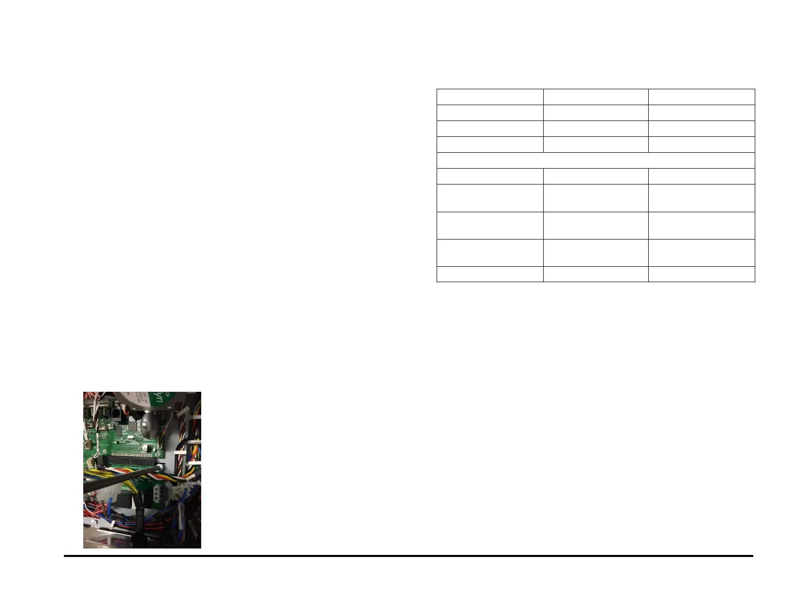
REP 5.2 Comm Board Replacement
PARTS LIST ON PL 7.1
Use this procedure to remove and install the Comm Board.
WARNING
Do not perform repair activities with the power on or electrical power
supplied to the machine. Some machine components contain
dangerous electrical voltages that can result in electrical shock and
possible serious injury. See Section 0, page vi for other languages.
Removal Procedure
1. Switch power OFF to entire printing system.
2. Disconnect the Power Cord.
3. Do REP 1.6 to remove the Rear Cover.
4. Disconnect the Connectors (3).
Connector J2
Connector J14
Connector J15
For DFA configurations, there will be (4) connectors.
Connector J1
Connector J6
Connector J14
Connector J15
5. Remove the Screws (3) and the old Comm Board.
Installation Procedure
1. Place the new Comm Board in position and tighten the Screws (4).
2. Connect the Connectors (3).
3. Do REP 1.6 to install the Rear Cover.
4. Connect the Power Cord.
5. Power ON the entire printing system.