GBC AdvancedPunch Pro 08/20/2015 Repairs/Adjustments
4-71
REP 2.25.7 Alignment Sensor Board (S11 – S15) Replacement
PARTS LIST ON PL 5.7
Use this procedure to remove and install the Alignment Sensor Board
(S11, S12, S13, S4, S15).
1. Switch power OFF to entire printing system.
2. Disconnect the Power Cord.
3. Do REP 1.6 to remove the Rear Cover.
4. Do REP 3.1 to remove the Punch Module.
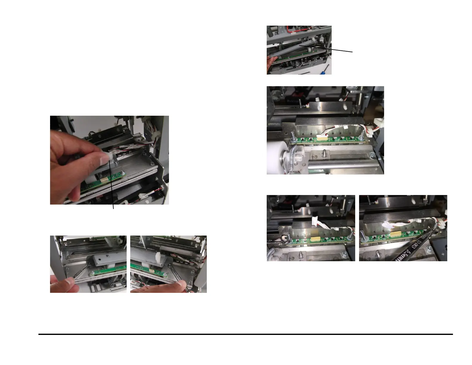
5. Disconnect the Skew Sensor Board Connector.
6. Release the Cable Clamp and move the Cable out of the way.
7. Remove the M4 Nuts (2).
8. Remove the Roller Cover.
9. Disconnect the Alignment Sensor Board Connector.
10. Release the Cable Clamp and move the Cable out of the way.
11. Remove the M4 Nuts (2) and Washers (2),
12. Remove the Alignment Sensor Board.
Skew Sensor Board Connector