GBC AdvancedPunch Pro 08/20/2015 Repairs/Adjustments
4-119
5. Electronics and Control
REP 5.1 Main Control Board Replacement
PARTS LIST ON PL 7.1
Use this procedure to remove and install the Main Control Board. Before
replacing the Main Control board, attempt to retrieve the number of Punch
cycles, do GP 6.1.11 Punch Cycles Procedure.
Removal Procedure
WARNING
Do not perform repair activities with the power on or electrical power
supplied to the machine. Some machine components contain
dangerous electrical voltages that can result in electrical shock and
possible serious injury. See Section 0, page vi for other languages.
1. Switch power OFF to entire printing system.
2. Disconnect the Power Cord.
3. Do REP 1.6 to remove the Rear Cover.
4. Remove the M3 Screws (4) from the Main Control Board and the
Comm Board.
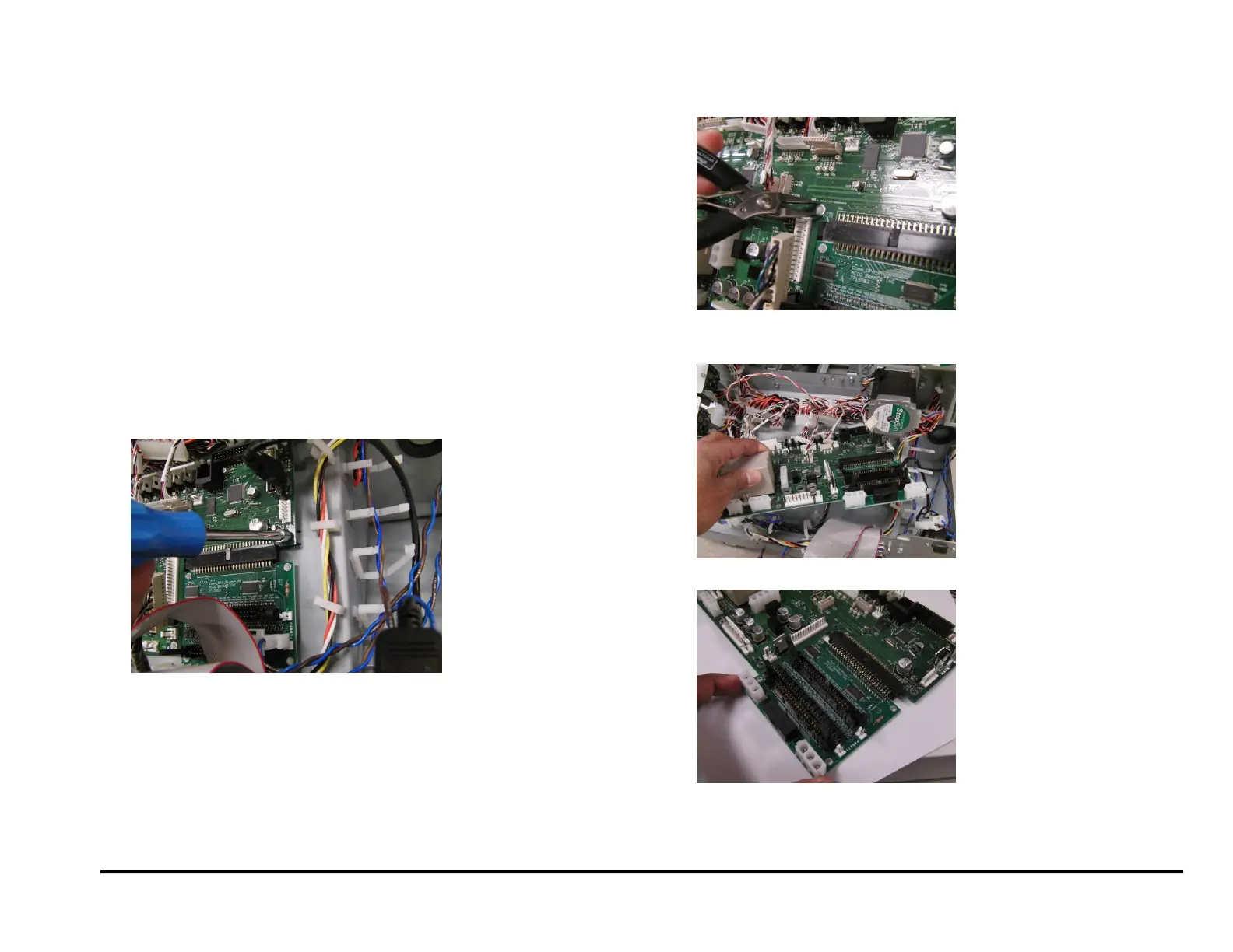
5. Use pliers to release the plastic Standoffs (9).
6. Disconnect the Connectors (24).
7. Remove the old Main Control Board and Comm Board.
8. Disconnect the Connector and remove the Comm Board.
Note: DFA Comm Board shown in above images.