EasyManua.ls Logo

GBC AdvancedPunch Pro - Page 208

GBC AdvancedPunch Pro
400 pages
Print Icon
To Next Page IconTo Next Page
To Previous Page IconTo Previous Page
Loading...
Repairs/Adjustments 08/20/2015 GBC AdvancedPunch Pro
4-120
Installation Procedure
1. Install the the Comm Board on the Main Control Board and connect
the Connector.
2. Place the new Main Control Board and Comm Board in position
3. Connect the Connectors (30), (31 if DFA)
Refer to the System Wiring diagram in Section 7.
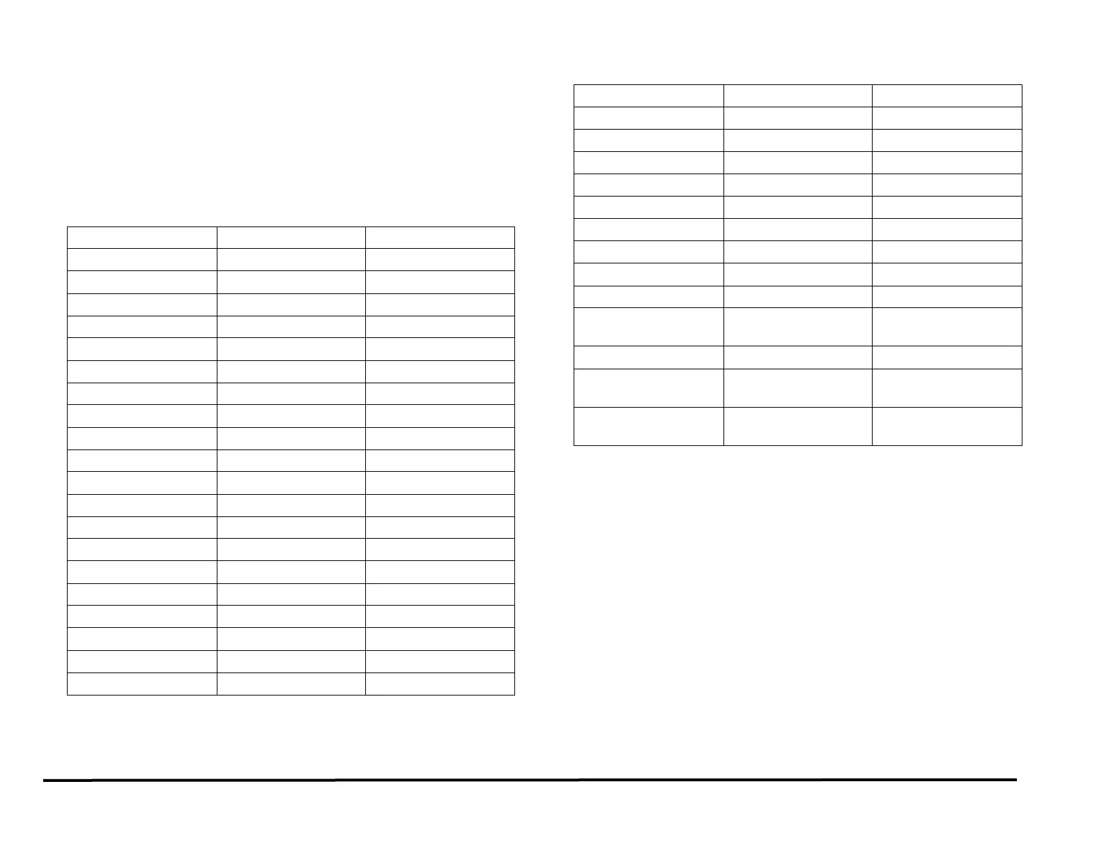
The following table lists the connectors starting at the top right and
going counterclockwise.
GBC Cable/Wire #
Xerox Cable/Wire#
Connector #
7715523
023N01337
J36
7715455
023N01349
J23
7715467
023N01352
J19
7715466
023N01351
J18
7715536
023N01355
J29
7715451
023N01343
J21
7715485
023N01327
J27
7715477
023N01339
J17
7715462
023N01342
J30
7715473
023N01334
J15
7715453
023N01346
J22
7715495
023N01331
J9
7715468
023N01333
J14
7715457
023N01345
J25
7715456
023N01344
J24
7715476
023N01340
J2
7715493
023N01322
J3
7715494
023N01321
J4
7715487
023N01332
J8
7715492
023N01329
J1
Cable/Wire #
Xerox Cable/Wire#
Connector #
7715459
023N01347
J28
7715458
023N01348
J26
7715267
127N07842
J20
7715470
023N01323
J16
7715538
023N01328
J37
7715490
023N01356
USB Connector
7715537
023N01330
J12
7715548
152N11850
J2 COMM Board
7715498
023N01336
J14 COMM Board
7715535 DFA
J14 COMM Board-
DFA
7715494
023N01321
J15 COMM Board
7715532 DFA
J1 COMM Board-
DFA
7715531 DFA
J6 COMM Board-
DFA
4. Use pliers to install the plastic Standoffs (9).
5. Tighten the M3 Screws (4) in the Main Control Board and the Comm
Board.
6. Do REP 1.6 to install the Rear Cover.
7. Connect the Power Cord.
8. Power ON the entire printing system.

Table of Contents