GBC AdvancedPunch Pro 08/20/2015 Repairs/Adjustments
4-109
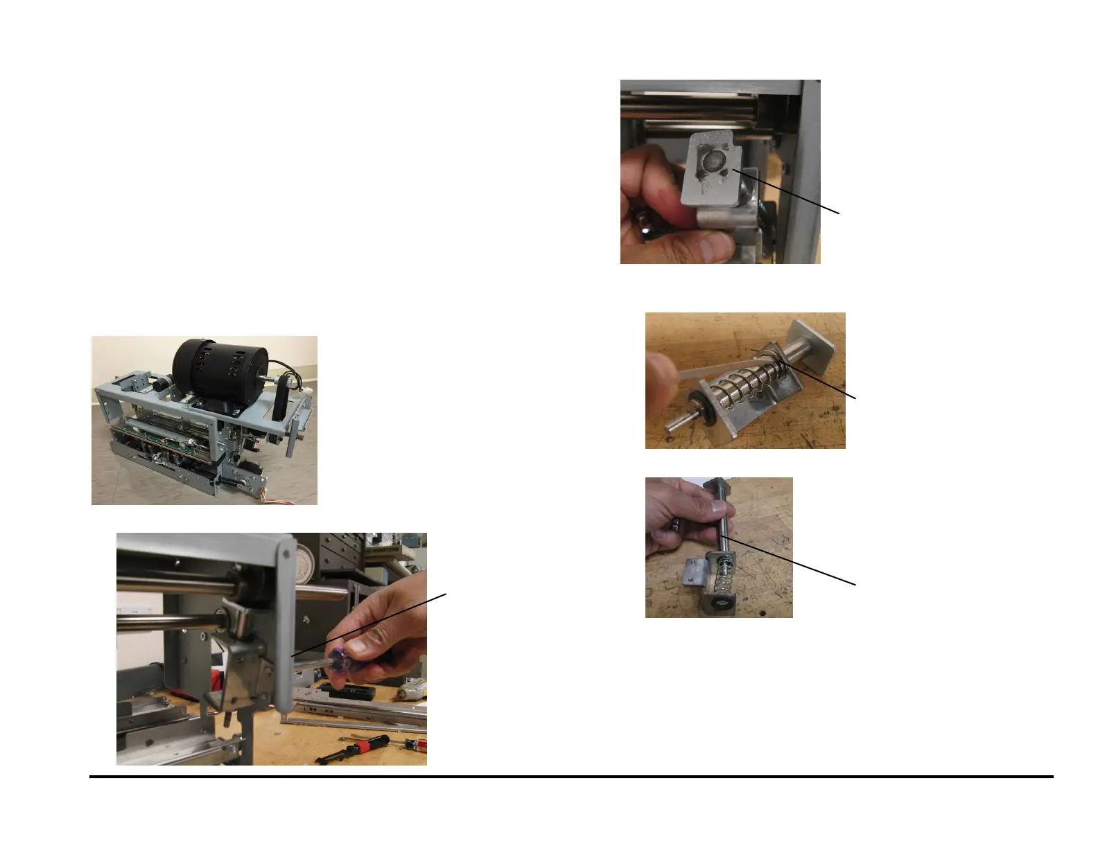
REP 3.13 Die Lock Plunger and Stripper Assembly Replacement
PARTS LIST ON PL 5.1 (page 2)
Use this procedure to remove and install the Die Lock Plunger and
Stripper Assembly or the Die Lock Bracket.
Removal Procedure
WARNING
Do not perform repair activities with the power on or electrical power
supplied to the machine. Some machine components contain
dangerous electrical voltages that can result in electrical shock and
possible serious injury. See Section 0, page vi for other languages.
1. Switch power OFF to entire printing system.
2. Disconnect the Power Cord.
3. Do REP 1.6 to remove the Rear Cover.
4. Do REP 3.1 to remove the Punch Module.
5. Remove the left or right Die Lock Bracket Screws (2).
6. Note the orientation of the Stripper Pad.
7. To replace the components in the Die Lock Plunger and Stripper,
Remove the E-Clip
Pull the Die Lock Plunger and Stripper out.
Installation Procedure
8. Install the Plunger and Stripper Assy.
9. Do REP 3.1 to install the Punch Module.
10. Do REP 1.6 to install the Rear Cover.
11. Connect the Power Cord.
12. Power ON the entire printing system.
13. .
Die Lock
Plunger
and
Stripper