GBC AdvancedPunch Pro 08/20/2015 Repairs/Adjustments
4-73
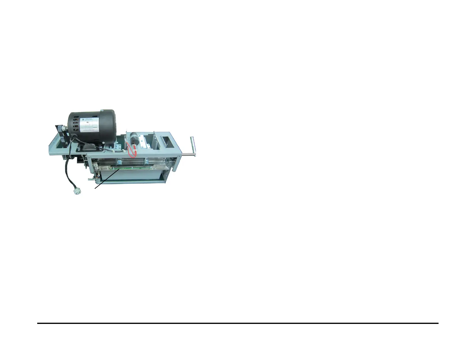
REP 2.25.8 Backage Sensor Board (S16, S17) Replacement
PARTS LIST ON PL 5.7
Use this procedure to remove and install the Backage Sensor Board
(S16, S17) or the Backage Sensor Bracket.
1. Switch power OFF to entire printing system.
2. Disconnect the Power Cord.
3. Do REP 1.6 to remove the Rear Cover.
4. Do REP 3.1 to remove the Punch Module.
5. Disconnect the Sensor Board Connector at the Board.
6. Remove the Nuts (3), Washers (3), and the Backage Sensor Board.
7. To replace the Lower Backage Sensor Bracket or the Bracket
Weldment,:
Open the Wire Saddles and remove the Sensor Cable.
Remove the M3 Nuts (2).
Remove the Bracket.
Remove the Bracket Weldment.
Place the new Bracket Weldment in position on the Studs (2)
Place the new Bracket in position in position on the Studs (2).
Tighten the M3 Nuts (2).
Place the Sensor Cable in the Wire Saddles, then close the wire
Saddles.
8. Place the new Backage Sensor Board in position.
9. Install the Washers (3) and tighten the Nuts (3)
10. Connect the Sensor Board Connector.
11. Do REP 3.1 to install the Punch Module.
12. Do REP 1.6 to install the Rear Cover.
13. Connect the Power Cord.
14. Power ON the entire printing system.