GBC AdvancedPunch Pro 08/20/2015 Repairs/Adjustments
4-69
REP 2.25.5 Double Punch (Large) Backage Sensor Board Assembly
(S18, S19) and Double Punch (X-Large) Backage Sensor Board
Assembly (S20, S21) Replacement
PARTS LIST ON PL 4.1
Use this procedure to remove and install the Backage Sensor Board
(S18, S19) or the Backage Sensor Board (S20, S21).
WARNING
Do not perform repair activities with the power on or electrical power
supplied to the machine. Some machine components contain
dangerous electrical voltages that can result in electrical shock and
possible serious injury. See Section 0, page vi for other languages.
1. Switch power OFF to entire printing system.
2. Disconnect the Power Cord.
3. Do REP 1.6 to remove the Rear Cover.
4. Do REP 3.1 to remove the Punch Module.
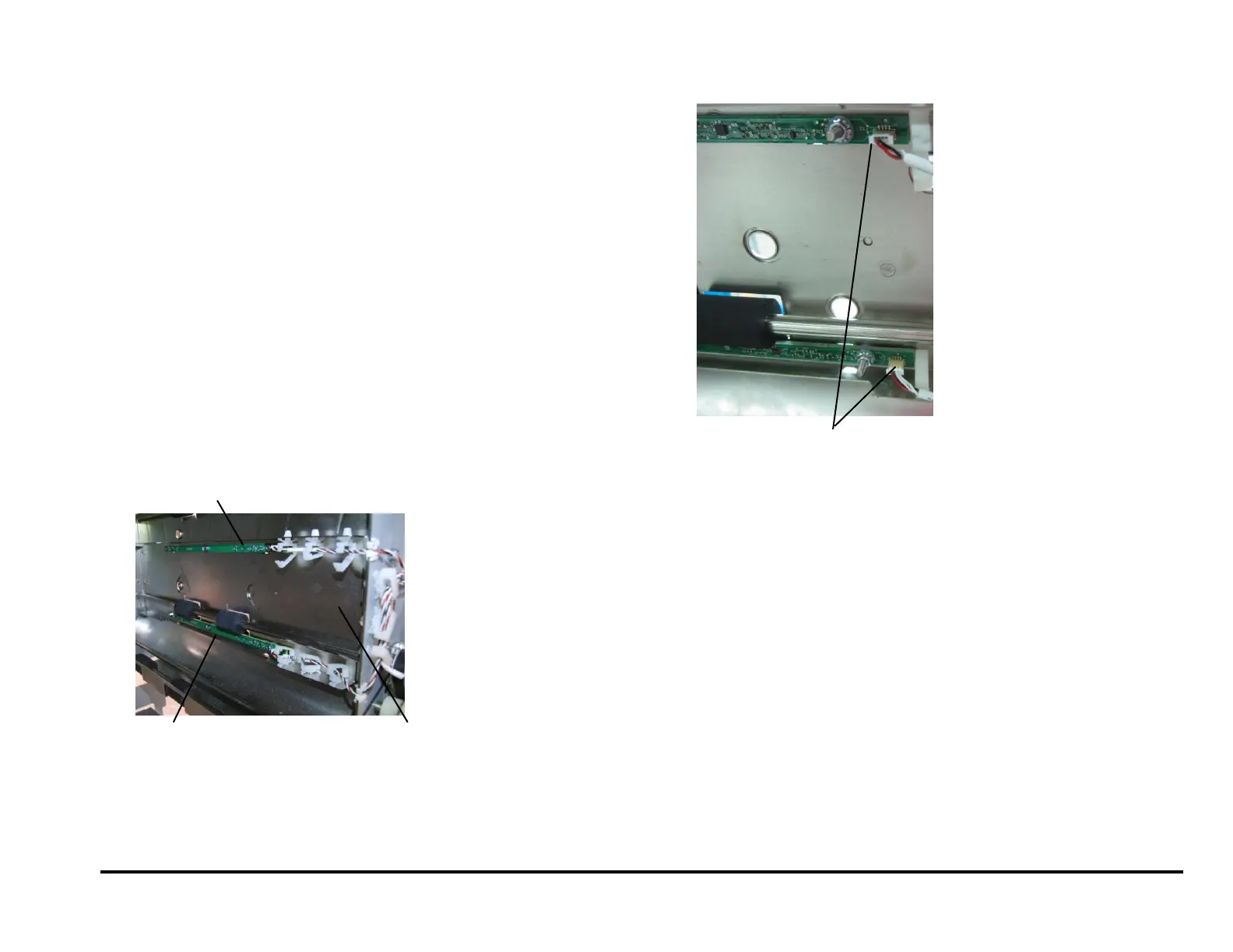
5. Locate the Drive Entrance Panel
The upper board is the Backage Sensor Board
(S20, S21).
The lower board is the Backage Sensor Board
(S18, S19).
6. Disconnect the Sensor Board Connectors (2).
7. Remove the Nuts (3) and Washers (3).
8. Remove the old Backage Sensor Board.
9. Place the new Punch Sensor Board in position.
10. Place the Washers (3) in position and tighten the Nuts (3).
11. Connect the Sensor Board Connector.
12. Do REP 3.1 to install the Punch Module.
13. Do REP 1.6 to install the Rear Cover.
14. Connect the Power Cord.
15. Power ON the entire printing system.
Backage Sensor Board
(S18, S19)
Backage Sensor Board (S20, S21)
Sensor Board Connector (2)