GBC AdvancedPunch Pro 08/20/2015 Repairs/Adjustments
4-29
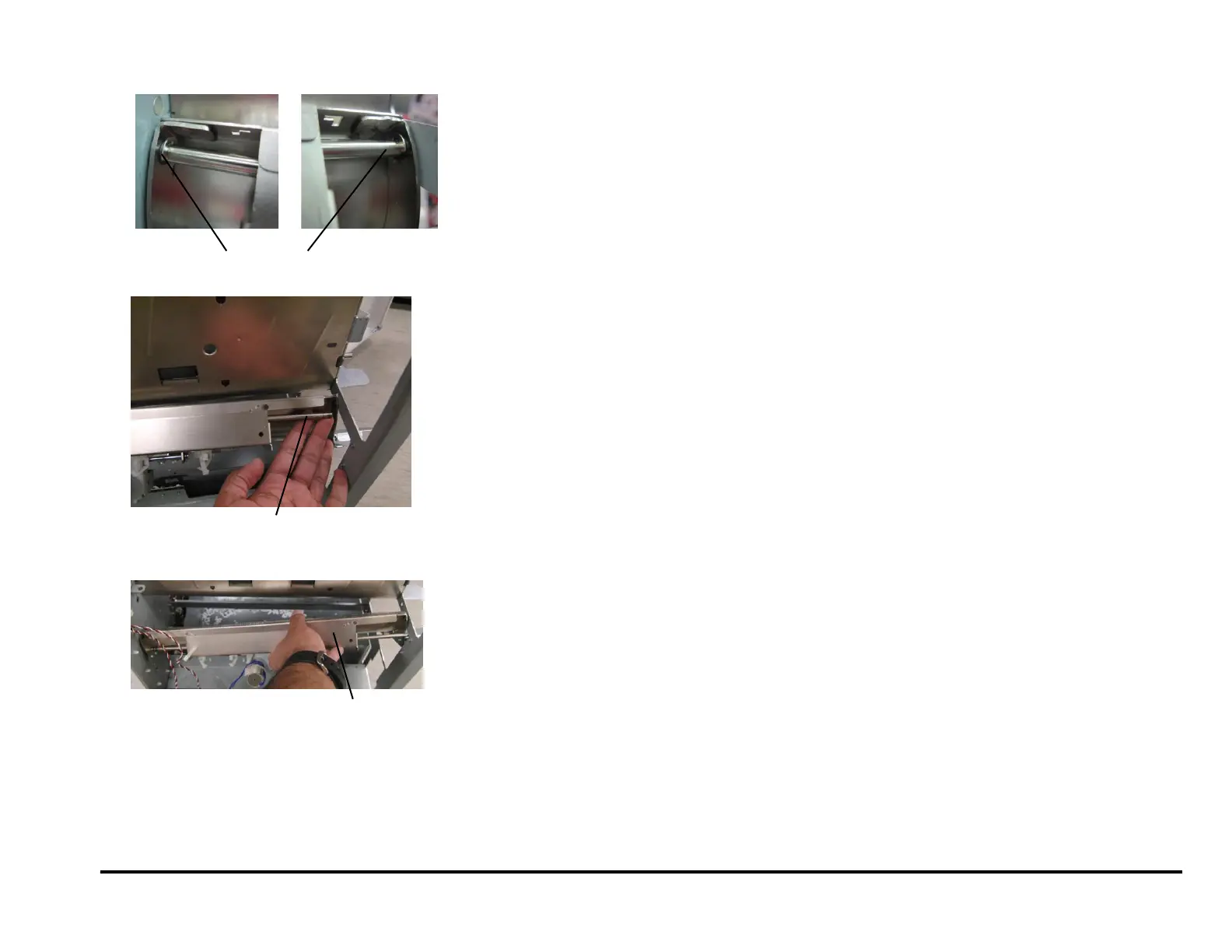
11. Remove the E-Ring (2) from each end of the Accel Idler Latch Shaft.
12. Remove the Accel Idler Latch Shaft.
13. Remove the Acceleration Idler Roller Assembly.
14. To replace the Accel Idler Panel Weldment do the following
procedures to remove and install these components.
REP 2.12 Acceleration Roller Idler Assembly Replacement
REP 2.25.3 Accel Sensor (S5) Replacement
REP 2.28.2 Disengaging Roller Solenoid Replacement
Installation Procedure
1. Place the Acceleration Idler Roller Assembly in position.
2. Slide the Accel Idler Latch Shaft through the holes in the frame and
the holes at each end of the Acceleration Idler Roller Assembly.
3. Install the E-Ring (2) at each end of the Accel Idler Latch Shaft.
4. Connect the Acceleration Idler Roller Solenoid SOL5 Connector at
the header.
5. Connect the Acccel Sensor S5 Connector.
6. Place the Cable in the cable Clamps and close the cable Clamps.
7. Grasp the Handle and close the Acceleration Idler Roller Panel.
8. Do REP 1.8 to install the Upstream Side frame Cover.
9. Close the Front Door.
10. Do GP 6.3 Dock the Punch to connect the Punch to the upstream
and downstream devices.
11. Connect the Power Cord.
12. Power ON the entire printing system.
Acceleration Idler Roller Assembly



 To Next Page