GBC AdvancedPunch Pro 08/20/2015 Repairs/Adjustments
4-117
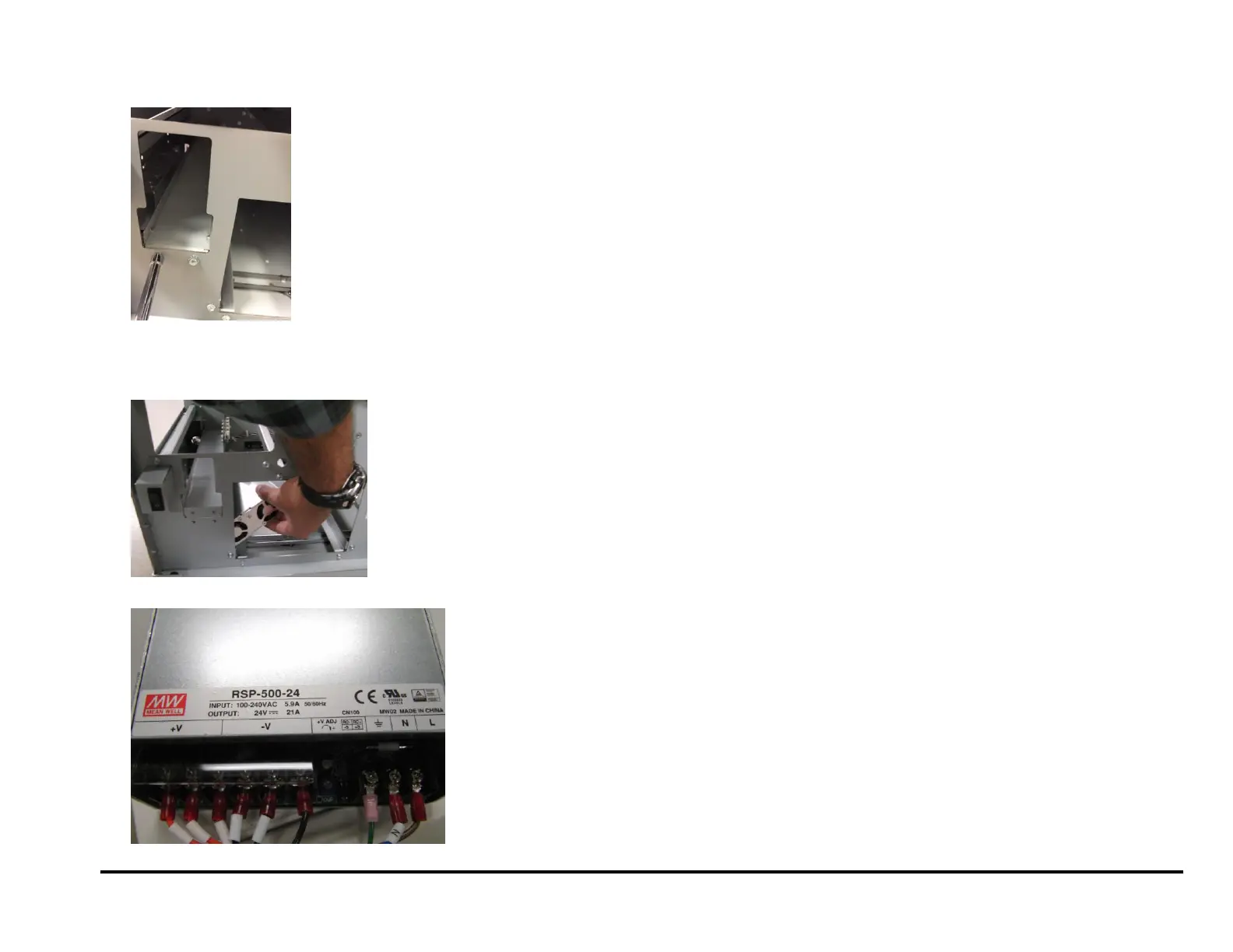
10. For DFA configurations- remove (2) M4 screws of the left side die
rack.
11. For DFA configurarations- Tilt the Power Supply and remove it
through the Chip Tray opening. The die rack (loosened in the above
step) has to bend up slightly to give room for the Power supply to be
removed.
12. Transfer all wires to the new Power Supply.
Installation Procedure
1. Reverse Steps for Installation.
 Loading...