Repairs/Adjustments 08/20/2015 GBC AdvancedPunch Pro
4-140
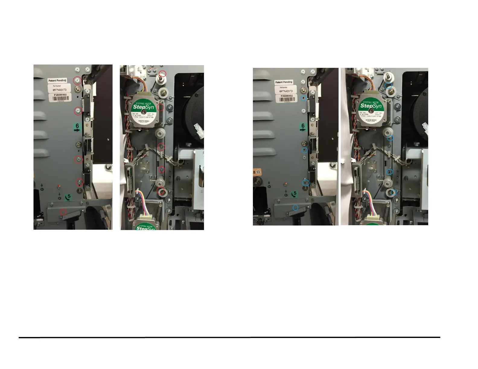
ADJ 1.8.2 Exit Drive Panel Position Adjustment
This drive panel controls the nip forces of N8, N9 and N10.
1. To adjust the position of the drive panel loosen (4) screws from the
Front frame and (4) screws from the rear frame
2. Using the Reference holes in the front/rear frame (4 holes in the front
frame and 4 holes in the rear frame) and the sheet metal panel,
position the drive panel to ensure the drive rollers protrude
1.5±0.5mm through the drive panel.