Chapter 5
Maintenance and Repair
P/N 57150002, Revision 5.0 5 - 93 Trimble S, VX, SPS & RTS Service Manual
F
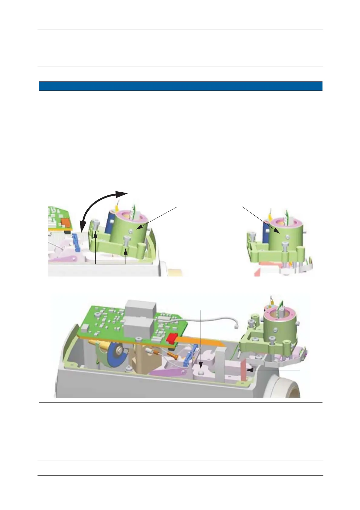
5 Remove the
transmitter unit.
A. ONLY REMOVE
THE TWO SCREWS
WITH SPRINGS.
B. Lift up the transmitter
unit and remove the
ball, see Fig. 5-91 on
page 5-93 .
C. Thread the tracker
transmitter board
carefully through the
gap, see Fig. 5-103 on
page 5-103 .
The other screws on
Transmitter unit
adjusts tracker
transmitter alignment.
Fig. 5-90 Removal of the Transmitter unit
Fig. 5-91 Insertion of the Tracker transmitter board TFB
Item Performance Action Result Notes
Transmitter unit including
Tracker transmitter
A
C
(Ball)
B