Service Parts Disassembly 8-109
Front Lift Uplink
Note
Two copper contacts are positioned between the frame and the Control Panel
bracket. Replace these contacts before securing the bracket to the frame.
1. Raise the Basket Assembly.
2. Remove the Waste Toner Reservoir, if installed.
3. Remove the Front Door (page 18).
4. Remove the Left Front Cover (page 21).
5. Remove the Upper Front Cover (page 22).
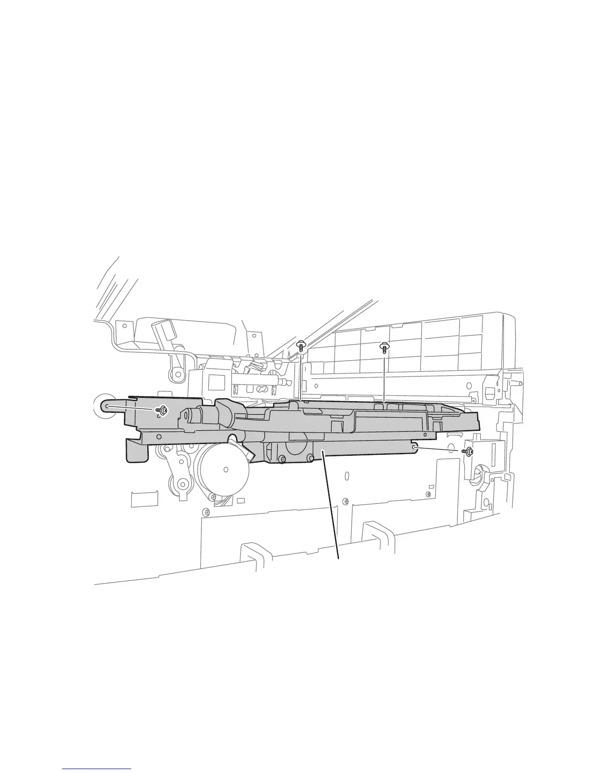
6. Remove 4 (metal, 6 mm) screws that secure the Control Panel bracket to the
frame.
7. Lower the bracket to access the Lift Uplink Cover.
Control Panel Bracket
s7400-657