EZ-USB FX3 Technical Reference Manual, Document Number: 001-76074 Rev. *F 217
Storage Ports
blockSize = glCardCtxt[portId].fnBlkSize[functionNumber];
}
else if (blockmode == CY_U3P_SDIO_RW_BYTE_MODE)
{
noOfBlocks = 1;
blockSize = (transferCount != 0) ? transferCount : 512;
}
Note: "blockmode" and "transferCount" are parameters passed to CyU3PSdioExtendedReadWrite. Whereas the variable
values "noOfBlocks" and "blockSize" are used to set the values of the registers-SDMMC_BLOCKLEN and
SDMMC_BLOCK_COUNT-the active SIB socket number for read/write is set using SDMMC_CS.SOCKET before initiating
reads/writes from/ to the SDIO device. The DAT0 pin state can be monitored to learn the storage device busy state by polling
for the bit SDMMC_SATUS.DAT0_STAT.
In a read opertion, the BLOCKS_RECEIVED and RD_DATA_TIMEOUT interrupts are cleared in the SDMCC_INTR register
by writing '1' to the bits. In a write operation, the BLOCK_COMP interrupt in the SDMMC_INTR register is cleared in the same
way.
Since CMD53 involves data phase, through DAT[0:3] lines, the DAT3_CHANGE interrupt is disabled by setting
SDMMC_INTR_MASK.DAT3_CHANGE. The interrupt is enabled again after command completion. Then command
transmission is initiated and completed in the same manner as described in Sending SD/MMC/SDIO Commands on
page 206.
In a CMD53 read operation, the command transmission is initiated by setting the bits SDMMC_CS. SNDCMD and
SDMMC_CS. RDDCARD, whereas in a CMD53 write operation, the command transmission is initiated by setting the bits
SDMMC_CS. SNDCMD and SDMC_CS. WRDCARD.
The data associated with the CMD53 data phase is read/written to/from the DMA channel associated with the socket ID
passed in for the operation. This operation should use one of the SIB sockets as a producer (for read) or consumer (for write).
Before calling this function, the necessary DMA channels need to be created. A DMA channel (out) is created to transfer data
to the SDIO device connected to any of the S-ports, and another DMA channel (in) is created to read data from the SDIO
device. Any of the six available S-port sockets can be used for these channels. Sockets are defined as follows inside the FX3
SDK library.
Transferring infinite blocks of data (by setting transferCount to 0 in block mode) is not supported on the FX3S devices. If
transferCount is set to 0, FX3S will transfer 512 bytes of data in multibyte transfer mode, but will throw an error in multiblock
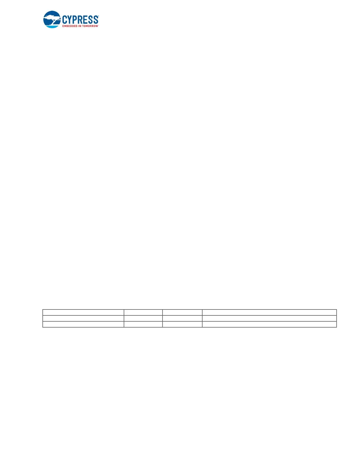
mode. Table 9-4 shows the number of bytes and blocks transferred based on transferCount values.
Table 9-4. Byte/ Block Count Values
The following code snippet demonstrates the use of this API.
CyU3PDmaChannelReset (&glChHandleSdiotoCpu);
size = ((length+511)/512)*512; /* make sure that size is 512 aligned */
dmaBuffer.size = size;
dmaBuffer.buffer = buff;
dmaBuffer.count = 0;
dmaBuffer.status = 0;
status = CyU3PDmaChannelSetupRecvBuffer (&glChHandleSdiotoCpu, &dmaBuffer);
if (status != CY_U3P_SUCCESS)
{
ERROR_PRINT (6, "CyU3PDmaChannelSetupSendBuffer error status = %d\r\n", status);
Transfer Count Value 0x000 0x001 0x002 ----- 0x1FF
Bytes Transferred 512 1 2 ----- 511
Blocks Transferred illegal 1 2 ----- 511

 Loading...


