Chapter 5
Maintenance and Repair
P/N 57150002, Revision 5.0 5 - 105 Trimble S, VX, SPS & RTS Service Manual
F
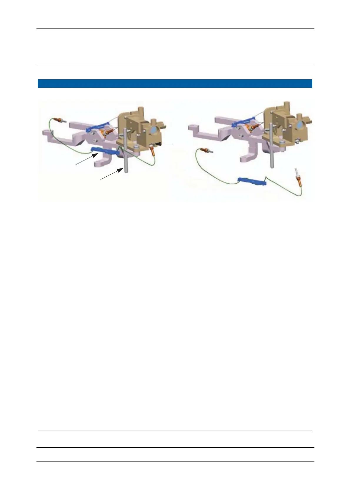
Fig. 5-105 Removal of reference fibre
8 Mount following units
to the new EDM
frame.
A. Push in reference fibre
to the end stop, see Fig.
5-105 on page 5-105
B. Mount the EDM base
screw, see Fig. 5-106
on page 5-106 . See
notes
C. Switch motor, see page
5-97.
D. Greywedge motor, see
page 5-99.
E. Transceiver board, see
page 5-95.
F. Transmitter unit, see
page 5-91.
Reference fibre is
adjusted at the other
end (Transmitter
unit).
The EDM base screw
should be mounted
without touching the
base.
9 Mount back
completed EDM High
Precision distance
unit.
A. Mount back the unit,
see Fig. 5-102 on page
5-102 and Fig. 5-103
B. Connect cable and
mount screws, see Fig.
5-101 on page 5-102 .
10 Position receiver fibre
and receiver fibre
holder.
A. Position fibre holder in
line with the EDM
frame.
B. Position receiver fibre
underneath the black
pad.
C. Make sure the receiver
fibre is no bending too
much, a radius of 15
mm is allowed.
Item Performance Action Result Notes
A
B
Reference fibre
with fibre holder
C