CCW-R-2**B INSTRUCTION MANUAL 11 CAUSES AND ACTIONS FOR ERRORS AND FAILURES
11-21
11.4 Troubleshooting
This section describes corrective action to take at the time when an error, failure or malfunction occurs,
and corrective action is targeted for maintenance engineers or Ishida service engineers who manage the
weighing machine.
<Trouble with error display>
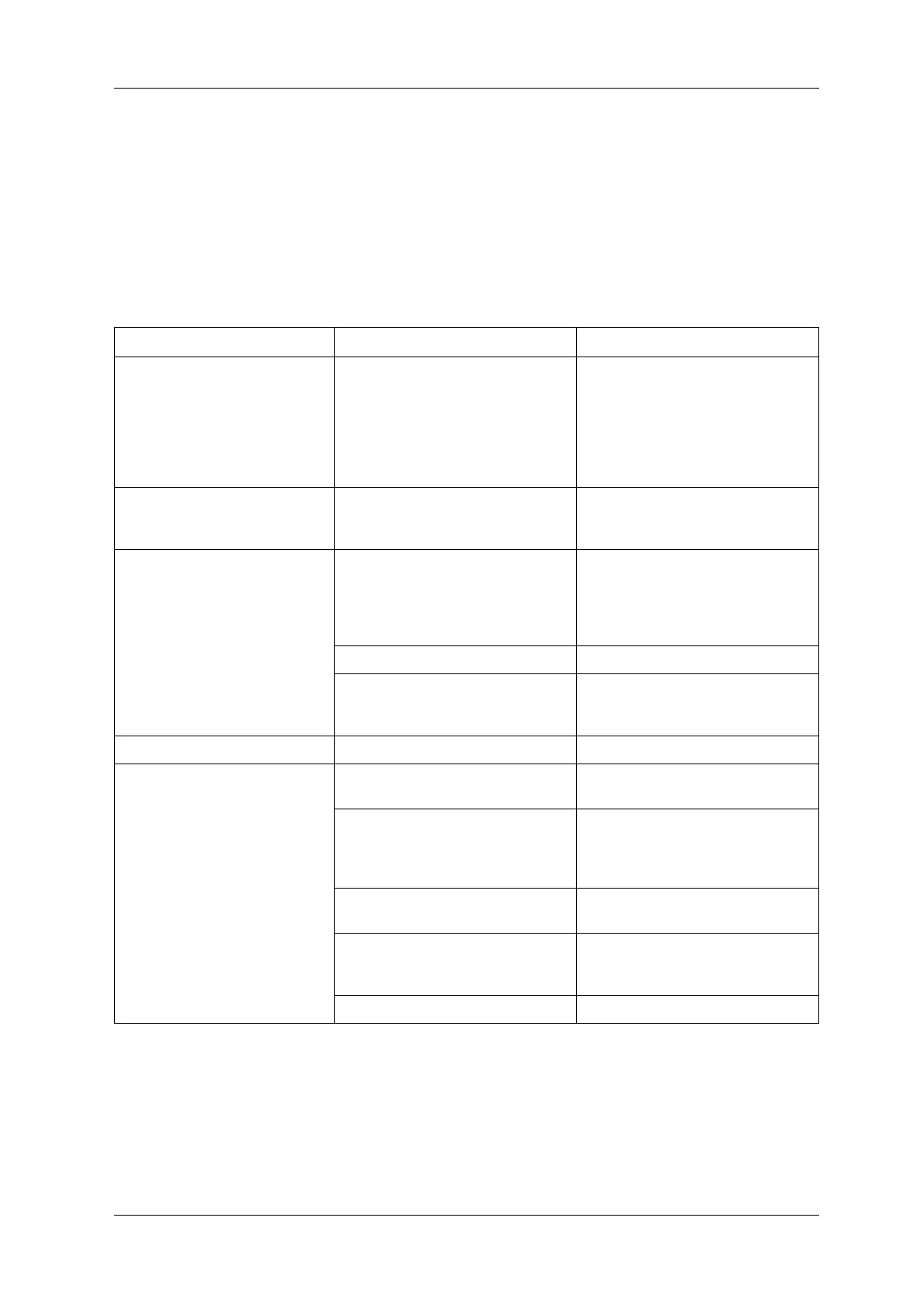
Table 11-11 Error, Failure and Malfunction List
Status Cause Action
[WARNING: NO TRANSMISSION]
(error display)
Connector breaking or poor connection. Check the conductivity of the following
connectors:
• J350 (ADC board P-5576*)
• XT601 (PS-0 unit)
• XJ455 (relay board P-5506*)
• XJ453 (relay board P-5506*)
• XJ384 (DMU board P-5562*)
[WARNING: NO RESPONSE] (error
display)
Connector breaking or poor connection. Check the conductivity of the following
connectors:
• XJ384 (DMU board P-5562*)
[ZERO ERROR]
(error display)
Board malfunction. • Replace the ADC board (P-5576*).
(When zero is unable to be obtained
even when J320 to J322 are
disconnected)
• Replace the preamp board (P-5527*).
Weigh mechanism malfunction. • Replace the load cell.
±15V power malfunction. • Check the ADC board (P-5576*) J324
connector.
• Replace the PS-CAL unit.
[SPAN ERROR] (error display) Board malfunction. • Replace the ADC board (P-5576*).
Hopper Error (PH, WH)
(error display)
There is a loose screw on the cam sensor
inside the weigh drive unit.
• Repair the weigh drive unit.
Board malfunction. • Replace the cam sensor board (P-
5207*).
• Replace the DUC board (P-5579*/P-
5524*).
Connector breaking or poor connection. • Check the conductivity of the DUC
board (P-5579*/P-5524*) connector.
The fuse in the main body is blown.
(PS-0 unit)
• Replace the midget fuse on the DC fuse
board (P-5508*) (PS-0 unit).
(125V 5A)
Weigh drive unit malfunction. • Repair or replace the weigh drive unit.
 Loading...