Home
ISHIDA
Industrial Equipment
CCW-R-2 B Series
ISHIDA CCW-R-2 B Series User Manual
5
of 1
of 1 rating
492 pages
Give review
Manual
Specs
To Next Page
To Next Page
To Previous Page
To Previous Page
Loading...
CCW-R-2**
ï¼¢
INSTRUCTION MANUAL
4 OPERA
TION PROCEDURES
4-25
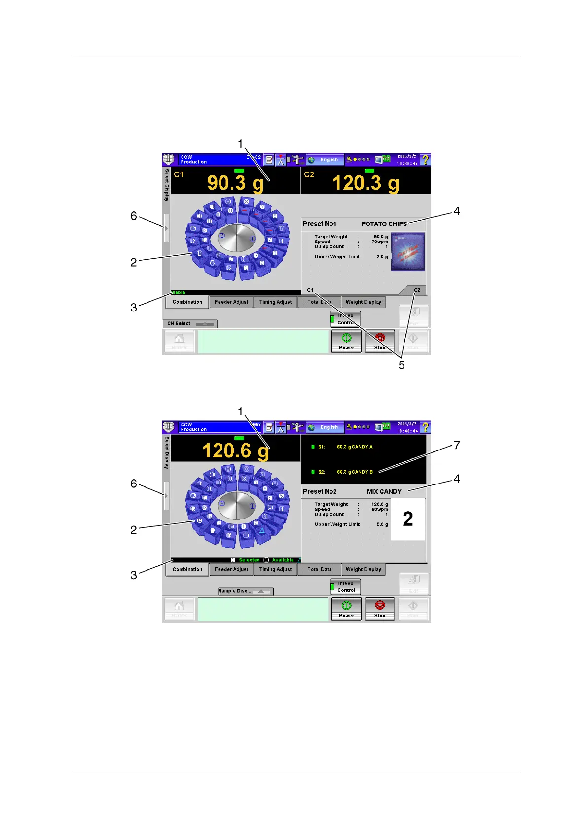
4.5.1
[Combination] Screen
T
o display the [Combination] screen, press the
[Combination] tab on the [Productio
n] screen.
Fig.4-45 [Combin
ation] Screen ([Producti
on] Screen, Double Weigher)
Fig.4-46 [Comb
ination] Screen
([Production] Scree
n, Mix Weigher)
70
72
Table of Contents
Table of Contents
9
Safety Precautions
21
Warning Terms and Meaning
22
General Precautions
23
Special Precautions
25
Warning Label
26
Warning Label Handling
26
Attached Locations of Warning Labels
26
Power Supply Shut off and Indication
27
Introduction
29
Intended Use of the Device
29
Features of the Device
30
Specifications of the Device
31
Standard Specifications
31
Outside Dimension
31
Operation Environment
31
Term Description
32
Components of the Device
34
Operation Outline
36
Operating Panels
37
Items and Functions of Remote Control Unit
38
Operation Panel and Data Input
39
Operation Panel
39
Data Input
43
Inputting Figures
44
Inputting Alphanumeric Characters and Symbols
45
Correcting Confirmed Contents
46
Operation Procedures
47
Emergency Stop and Restart
48
Outline of the Production
49
Production Procedures
50
Pre-Start Inspection
50
Air Pressure Adjustment (WP Specification)
51
Turning the Device Power Switch on
52
Turning the Control Unit Power Switch on
52
Selecting the Machine Mode
53
Start-Up Assistant Function
55
Preset Selection
58
Zero Adjustment
62
Starting the Production
66
Stopping the Production
67
Discharging the Products
68
Turning the Device Power Switch off
69
Display During the Operation
70
Combination] Screen
71
Select Display] Pop-Up Menu in [Combination] Screen
73
Temporary Stop and Restart
75
Temporary Stopping
75
Restarting
75
Outputting the Operational Status
76
Every Combination Output
76
Current Total Output
78
Loading the Printer Paper
80
Handling Drive Unit
82
Registering of Products
83
Presetting the Double Weigher
84
Registration Details
84
Outline of the Registration
87
Preset Procedures
88
Selecting the Machine
88
Setting the Product
89
Setting the Speed
92
Setting the Weight Value
93
Presetting Other Channels
95
Presetting the MIX Weigher
96
Registration Details
96
Outline of the Registration
99
Preset Procedures
100
Selecting the Machine
100
Selecting the Section
101
Setting the Product
104
Setting the Weighed Product
107
Setting the Weight Value
110
Completing Preset Procedures
111
Preset Management
112
Functions of the Operation Screens
113
Operation Keys and Operation Levels
114
Upper Setting Bar
121
Message Board
123
Start-Up Assistant
127
Language Selection
128
Operation Level Selection
129
Switching to [Operator] Level
130
Switching to [Site Engineer] Level
131
Switching to [Installation] Level
132
Control Panel] Screen
133
Screen Control] Tab Screen
134
Password Set/Langslct Set] Tab Screen
136
Destination ID] Tab Screen
137
Memory Card Handling
139
[Date & Time Setting] Screen
140
Help Function
142
Main Menu] Screen
143
Select] Pop-Up Menu
145
Zero Adjustment] Screen
147
Production] Screen
149
Combination] Tab Screen
152
Select Display Pop-Up Menu
154
Feeder Adjust] Tab Screen
156
Timing Adjustment] Tab Screen
156
Total Data] Tab Screen
157
Weight Display] Tab Screen
159
Drain] Screen
160
Full Open Lock] Screen
162
Full Open Lock Operation
165
Feeder Adjustment] Tab Screen
168
Select Preset] Screen
169
Photo Display
169
List Display
170
Preset] Screen
172
Preset Basic Function
172
Finish Prdct Setting] Index Screen
174
Product] Tab Screen
175
Product Photo Taking Procedures
176
Machine] Tab Screen
178
Item] Tab Screen
180
Others] Tab Screen
182
Product Setting
183
Two or more Divisions in MIX Mode)
183
Feeder Adjustment] Index Screen
185
Timing Adjustment] Index Screen
187
Weight Setting] Index Screen
188
Target Weight
189
Upper Weight Limit
189
Lower Weight Limit
190
Preset Change Operation
191
Preset Output
192
Select Total] Pop-Up Menu
194
Current Total] Screen
196
X-Bar Chart] Screen
201
Weigher's Transitional Data] Screen
202
Per Head - Cmb. Participation Data] Screen
203
Total Setting] Screen
204
Operation Log] Screen
206
Feeder Adjustment] Screen
207
Switching Display in [Feeder Adjust] Screen
213
AFD Ctroll Mode
216
AFD Range Setting
221
Timing Adjustment] Screen
223
Machine Set] Pop-Up Menu
226
Manual Adjustment] Screen
227
Weighing Adjst] Tab Screen
227
Combi. Calcltn] Tab Screen
231
AFV Monitor] Tab Screen
232
Self-Diagnosis] Screen
234
Device Check] Tab Screen
235
In/Output Signal] Tab Screen
236
Network Analyze] Tab Screen
238
Program Number] Tab Screen
239
Test Drive] Tab Screen
240
Display & Data Manager] Screen
243
Layout Setting] Tab Screen
243
Preset Manager] Tab Screen
244
Selecting and Copying Preset
245
Copying All Preset
247
Selecting and Initializing Preset
249
Initializing All Preset
250
Machine Set Mngr] Tab Screen
252
Selecting and Copying Machine Setting Items
254
Copying All Machine Setting Items
255
Selecting and Initializing Machine Setting Items
257
Initializing All Machine Setting Items
258
Various Parameter Setting] Screen
260
Weigh Spec Set] Tab Screen
260
Combination Set] Tab Screen
262
Sectioning Set] Tab Screen
264
Weigher Setting] Screen
265
Active Head] Tab Screen
265
AFD Setting] Tab Screen
266
Peripheral Equipment Setting] Screen
267
Pckr Intrlck Set] Tab Screen
267
Pckr Intrlck Set] Index Screen
268
Ringshutter] Index Screen
270
Divertingtiminghppr] Index Screen
272
Timinghopper] Index Screen
272
Infeedr Cntl Set] Tab Screen
273
Useful Functions
275
New Product Registration by Using Registered Product Data
276
Copying C1 Product Data to C2
276
Copying and Editing Registered Product Data
279
Reducing Product Change Time
281
Using Feeder Adjustment of Drain Function
281
Using Full Open Lock Function
282
Stopping Production of C1 Alone During C1 and C2 Production (One-Side Production Stop)
285
Stopping Production of C1 Alone
285
Comparing Values on Remote Control and Actual Values
287
Checking each Section in MIX Weigher
287
Optional Functions
289
Parent and Child Weighing
290
Types of Parent and Child Weighing
290
Parent and Child MIX Weighing
290
Bonus Adding
291
Setting Items of Parent and Child Weighing
291
Setting Procedures of Parent and Child Weighing
295
Production] Screen of Parent and Child Weighing
298
Count Set Weighing
300
Setting Items of Count Set Weighing
300
Piece Weight Revision
302
Setting Procedures of Count Set Weighing
304
Select Display] Pop-Up Menu (Count Set Weighing)
306
Output During Count Set Production
308
Cleanup Procedures
311
Washing and Sterilization
312
Washing and Sterilization Methods
314
Washing and Sterilizing of Components
317
Washing Removable Unit
317
Inlet Chute
318
Dispersion Table
319
Radial Trough
320
Pool Hopper, Weigh Hopper, and Booster Hopper
321
Collection Chute
322
Discharge Chute
323
Timing Hopper
324
Cleaning the Unremovable Unit
325
Main Body, Dispersion Portion, and Drive Unit
326
Remote Control Unit
328
Maintenance and Inspection
329
Daily Inspection
330
Pre-Start Inspection
330
Dispersion Table
331
Radial Trough
331
Confirming the Dew-Point Checker of the Air Dryer
332
Periodical Inspection
333
Inspection of Span (Monthly)
334
Span Adjustment
337
Inspection of Open/Close for Hopper Gate (Monthly)
340
Inspection of Open/Close Roller for Hopper (Monthly)
342
Inspection of Amplitude Strength for Radial Feeder (Monthly)
342
Inspection for Cracks (Annually)
343
Inspection of Rubber Cover (Annually)
344
Replacement of Memory Backup Battery
345
Replacement of Fuses
346
Replacement of the Air Dryer Element (WP Specification)
347
Replacement of the Air Dryer Module Set (WP Specification)
348
Causes and Actions for Errors and Failures
349
Error Display and Action
351
Pattern 1
353
Pattern 2
356
Pattern 3
358
Pattern 4
361
Pattern 5
362
Pattern 6
362
Pattern 7
363
Pattern 8
363
Error Clear and Action
364
Failure and Malfunction of the Weighing Machine
365
Troubleshooting
369
Installation
375
Installation Condition
376
Transportation and Lifting
377
Precaution for Transporting
377
Precaution for Lifting
378
Weight of Device, Center of Gravity, and Dimensions
379
Lifting Procedure
380
Installation Procedure
381
Unpacking Procedure
382
Checking Weighing Machine
382
Carrying in and Installing the Weighing Machine
382
Connecting Power Cable and Remote Control Unit
383
Installing Timing Hopper Frame
385
Connecting TH Signal Wire
385
Installing Timing Hopper
386
Installing Discharge Chute
386
Installing Collection Chute
386
Installing Radial Trough
387
Installing Dispersion Table
387
Installing Booster Hopper
387
Installing Weigh Hopper
388
Installing Pool Hopper
388
Connecting to Interlocking Device
389
Check and Adjustment after Installation
391
Checking Assembly Condition of each Unit
392
Turning the Power on
394
Changing the Operation Level
395
Zero Adjustment
396
Span Adjustment
398
Check Items at Installation
400
Appendix
403
Electrical Unit Layout Drawing
404
Electrical Unit Layout Drawing (CCW-R-216B)
404
Electrical Unit Layout Drawing (CCW-R-224B)
405
Overall Block Diagram
406
Remote Control BOX Unit
407
RCU Board (P-970*)
408
PRN Board
410
TP-I/F Board (P-5573*)
411
Main Electrical Unit
412
HUB Board (P-5535*)
413
MPS Board (P-5436*)
414
FDRV Board (P-5578*)
415
FDC Board (P-5532*)
416
Main Electrical Unit (CCW-R-224B)
417
Main Electrical Unit 1
417
HUB Board (P-5535*)
418
FDRV Board (P-5578*)
419
FDC Board (P-5532*)
420
Main Electrical Unit 2
421
MPS Board (P-5436*)
422
Preamp Board (P-5435*)
423
Base Unit Feeder
424
Preamp Board (P-5435*)
424
AFV Unit
425
AFV Preamp Board (P-5488*)
425
Relay Unit
426
EXC Board (P-5426*)
427
Relay Board (P-5506*)
429
Relay Unit (CCW-R-224B)
429
EXC Board (P-5426*)
430
Relay Board (P-5506*)
432
Additional Relay Unit (CCW-R-224B)
432
EXC Board (P-5426*)
433
Relay Board (P-5506*)
434
Unit
435
Unit (CCW-R-224B)
436
Unit
438
Unit (CCW-R-224B)
439
Weigh Drive Unit
440
DUC Board (P-5428*)
440
DDU Board (P-5439*)
442
Cam Sensor Board (P-5207*)
442
Booster Hopper Drive Unit
443
DU Board (P-5429*)
443
Cam Sensor Board (P-5207*)
443
CAL Unit
444
ADC Board (P-5576*)
445
WCU Board (P-5561*)
446
DMU Board (P-5562*)
447
CAL Unit (CCW-R-224B)
449
ADC Board (P-5576*)
449
WCU Board (P-5561*)
451
DMU Board (P-5562*)
452
PS FEEDER Unit
454
FPS Board (P-5580*)
455
FPS Board (P-5581*)
456
PS FEEDER Unit (CCW-R-224B)
457
PS FEEDER Unit 1
457
FPS Board (P-5580*)
458
PS FEEDER Unit 2
459
FPS Board (P-5580*)
460
Connection Diagram
461
Total Diagram
461
Block Diagram
461
Connection Diagram (CCW-R-224B)
462
Total Diagram
462
Block Diagram
462
5
Based on 1 rating
Ask a question
Give review
Questions and Answers:
Need help?
Do you have a question about the ISHIDA CCW-R-2 B Series and is the answer not in the manual?
Ask a question
ISHIDA CCW-R-2 B Series Specifications
General
Brand
ISHIDA
Model
CCW-R-2 B Series
Category
Industrial Equipment
Language
English
Related product manuals
ISHIDA CCW-R-224B-14-SS
492 pages
ISHIDA CCW-R-224B-15-SS
492 pages
ISHIDA WM-4000
85 pages