CCW-R-2**B INSTRUCTION MANUAL 13 APPENDIX
13-3
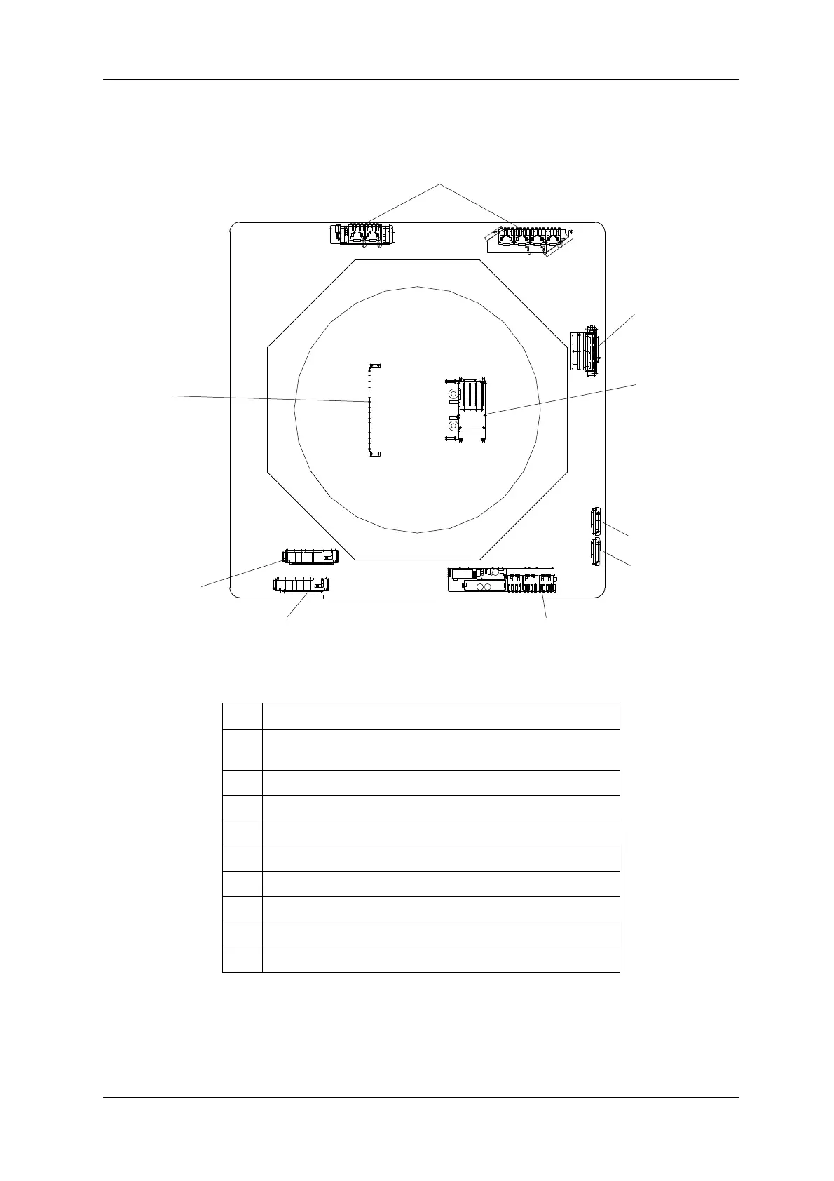
13.2.2 Electrical Unit Layout Drawing (CCW-R-224B)
Fig.13-2 Electrical Unit Layout Drawing
Table 13-2 Names of Electrical Unit Parts
No. Name
1 Electrical unit 1
(HUB board, FDRV board, FDC board)
2 Electrical unit 2 (MPS board)
3 CAL unit (ADC board, WCU board, DMU board)
4PS-0 Unit
5PS-2 Unit
6 RELAY unit (EXC board, RELAY board)
7 SUB RELAY unit
8 PS-FEEDER unit 1
9 PS-FEEDER unit 2
 Loading...