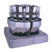
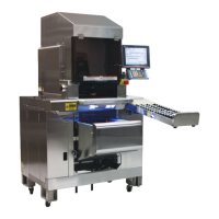
CCW-R-2**B INSTRUCTION MANUAL 12 INSTALLATION
12-15
12.4.15 Connecting to Interlocking Device
Connect the interlock signal wires of the relay unit to the interlocking device such as packer and feeder.
• When other devices need to be connected before and after this weighing
machine, shut off the power for all of the devices. Failure to do so may cause
an electrical shock.
• In order to prevent malfunction of the weighing machine, route the interlock
signal wire away from the power cables.
When using relays and contactors as a load, prevent induction noise by using
a surge killer or other methods.
(1) Specifications of the interlocking device signal
For the interlocking device signals, follow the specifications below.
Table 12-4 Specifications of the Interlocking Device Signal
Interlock Target Signal Input/Output Characteristics of the
weighing machine
1. Packer • Interlock signal.
The interlock signal from the packer to the
weigher should output a no-voltage contact
signal.
• Input characteristics.
Circuit: opto-isolator.
Voltage: 24VDC.
Current: approx. 15 mA.
Signal width: min. 50 msec.
• Discharge completion signal.
The discharge completion signal from the
weigher to the packer outputs a no-voltage
contact signal.
• Output characteristics.
Circuit: relay contact.
Rating: connect 250V, the load of AC5A or
lower.
Signal width: set arbitrary with the remote
control.
(Default value is 100 msec)
2. Infeeder • Infeed control signal.
The feed signal from the weigher outputs a no-
voltage contact signal.
• Output characteristics.
Circuit: relay contact.
Rating: connect 250V, the load of AC5A or
lower.
3. Other • Error signal.
The error signal from the weigher outputs a no-
voltage contact signal.
• Output characteristics.
Circuit: relay contact.
Rating: connect 250V, the load of AC5A or
lower.
 Loading...