12 INSTALLATION CCW-R-2**B INSTRUCTION MANUAL
12-10
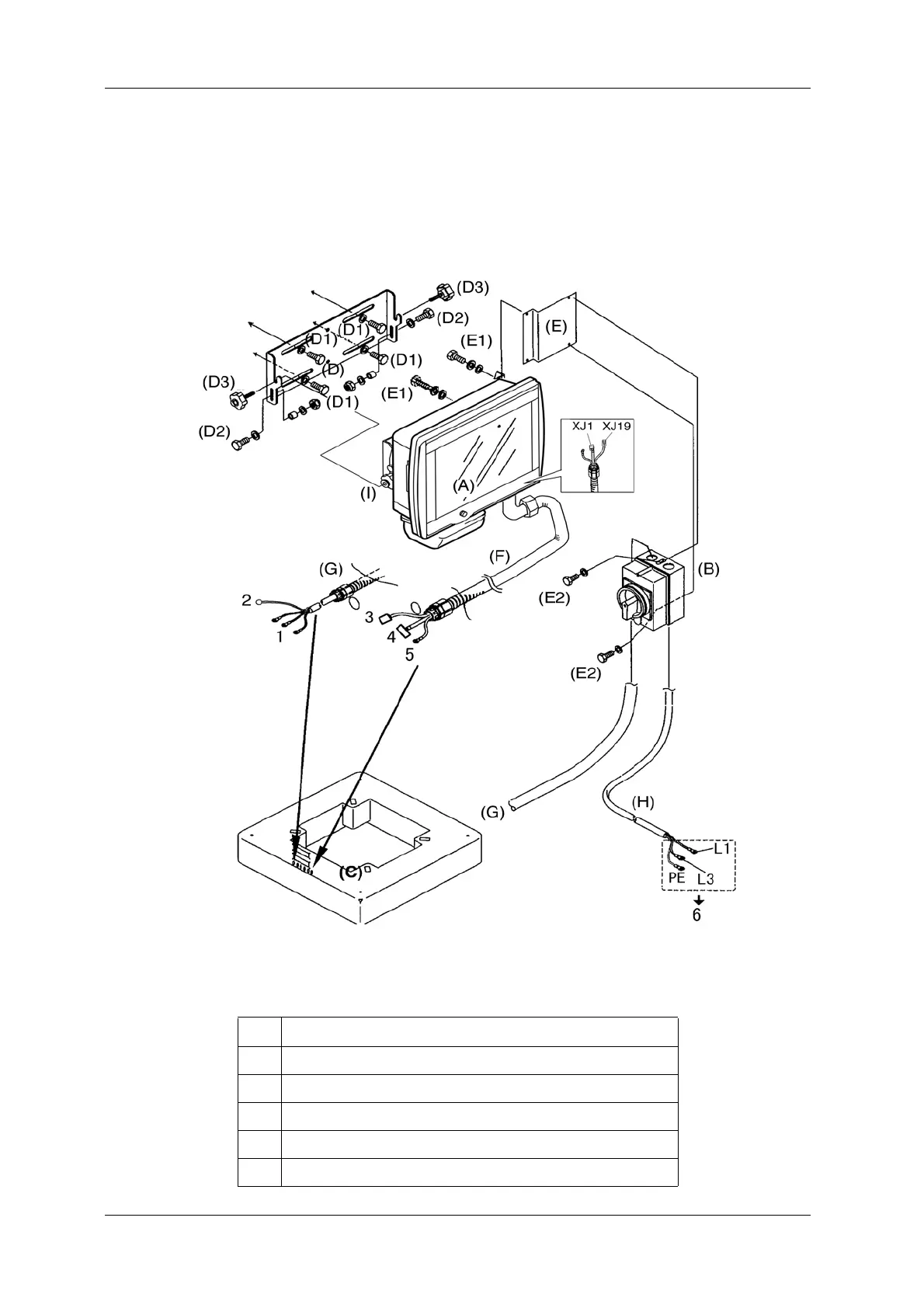
7. Connect the RCU power cable XC21 of the remote control cable (F) to U01 of the PS-0 unit located
in the main body frame. Connect the ground wire to the PS-0 unit grounding block.
8. Connect the customer power source side of the power cable (H) to the plant power terminal (outlet)
that is closest to the weighing machine.
Fig.12-2 Wiring Diagram for Power Cable Remote Control Unit
Table 12-3 Power Cable Connecting Locations
No. Connecting Location
1 PS-0 unit (Terminal block XT601)
2 PS-0 unit (QF2, primary side)
3 PS-0 unit (U01-XC21 connector)
4 Ethernet relay connector
5 Ground terminal block
 Loading...