Chapter 6
Adjustment and verification
Trimble S, VX, SPS & RTS Service Manual6 - 56 P/N 57150002, Revision 5.0
F
6 Align transmitter
beam (laser pointer) to
infinity.
A.Remove the screen at-
tachment and the reticle
illumination.
B. Remove the greyfilter
from the collimator.See
Fig. 6-102 on page 6-
93
C. Aim with the
instruments cross-hair
to the collimator cross-
hair and Click Holding
mode
ON. See Fig. 6-
46 on page 6-54
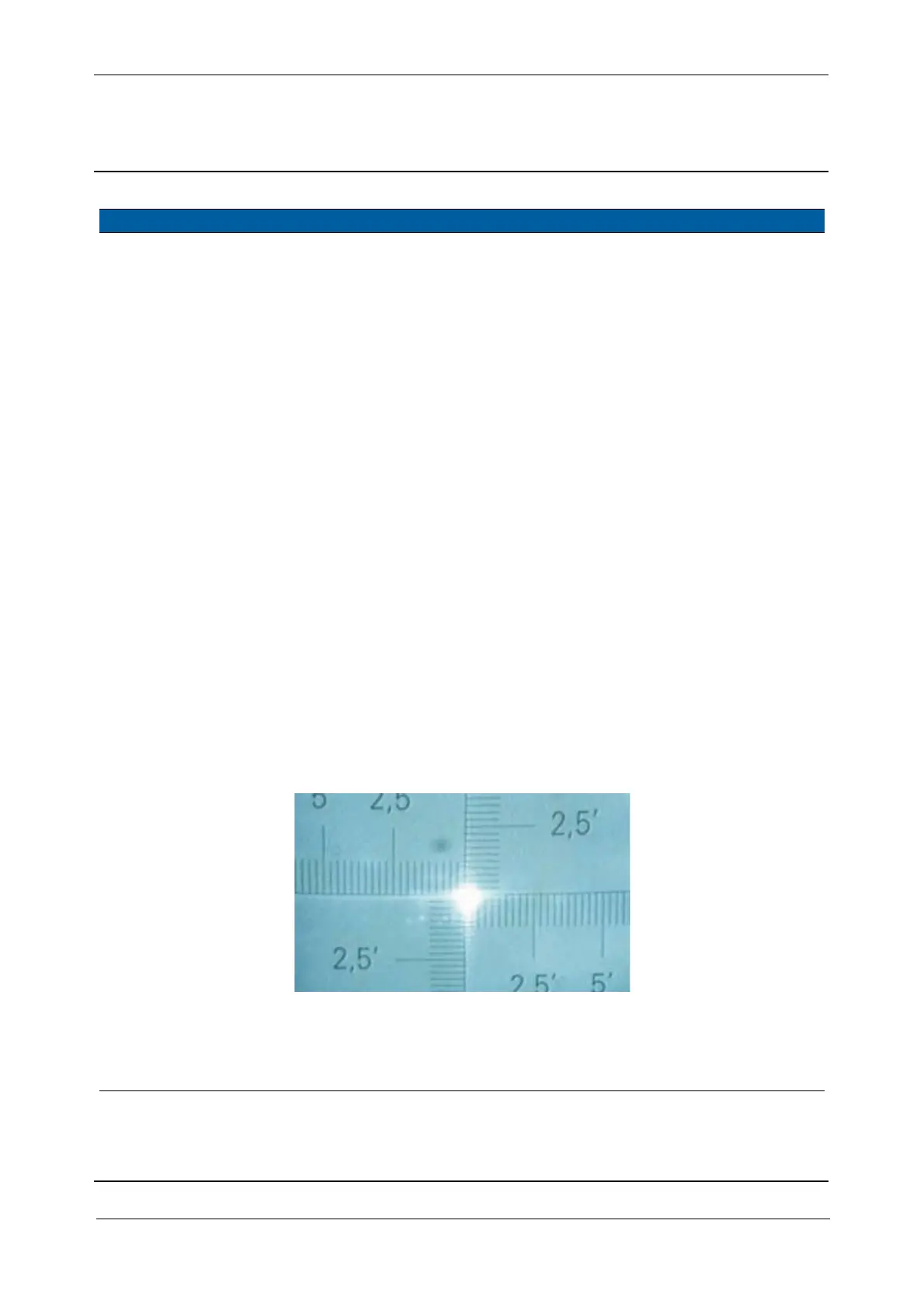
D. Move in the greyfilter
of the collimator to see
the transmitter spot on
screen,See Fig. 6-49 on
page 6-56
E. Adjust half the
deviation of the spot by
adjusting the vertical
and horizontal
adjustment screw.See
Fig. 6-45 on page 6-53
F. Loosen screws and
adjust the other half by
moving the EDM
frame, see item 5See
Fig. 6-47 on page 6-55
Deviation from
centre < 10“
(1/3 of a gradu-
ation on the col-
limators cross-
hair).
Fig. 6-49 Laser pointer Spot on collimator
7 Check position of
transmitter beam spot
on the transmitter
prism, again.
See Fig. 6-48 on page 6-55
.
Item Performance Description Result Notes