Phaser 6300/6350/6360 Color Laser Printer Service Manual 8-27
Service Parts Disassembly
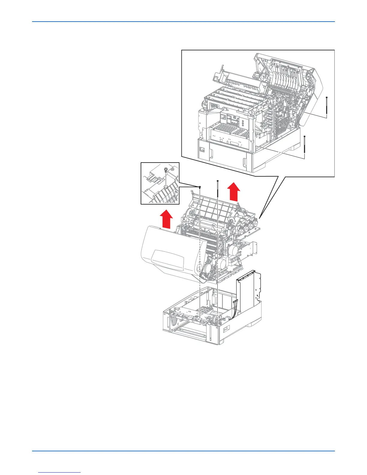
16. Remove 3 long screws that secure the chassis at the rear left corner, front
left corner near the base of Door A, and the front right corner.
17. Remove the Registration Roller Assembly (page 8-41).
18. Loosen the Registration Chute (page 8-37) to provide access to the screw
(metal, 6 mm) located directly underneath that secures the printer frame
to the Tray 2 Paper Pick Assembly.
19. Loosen the harnesses of (P/J17) and (P/J47) from the slit in the bottom
plate.
20. Lift the chassis by the frame and separate it from Tray 2.
Replacement Note
Verify that the Power Switch linkage is in place prior to securing the
support.
s6360-38