8-26 Phaser 6300/6350/6360 Color Laser Printer Service Manual
Service Parts Disassembly
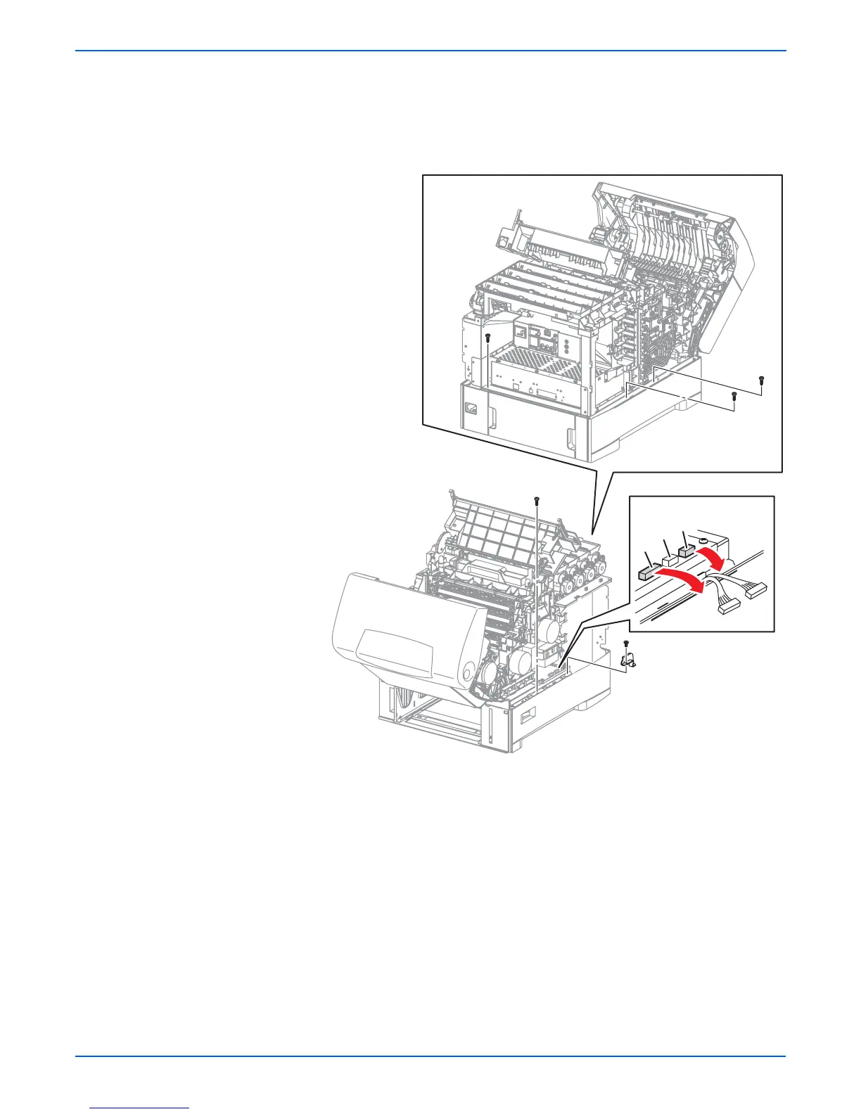
14. Remove the 1 screw (silver, 6 mm) that fixes the Power Switch Link
Support Bracket and remove the bracket.
15. Unplug connectors (P/J17 and P/J47) from the Engine Control Board.
16. Remove the 4 screws (self-tapping, plastic 10 mm) located around the
perimeter of the chassis.
s6360-383
47
60
17