Phaser 6300/6350/6360 Color Laser Printer Service Manual 2-45
Theory of Operation
Electrical
o
e
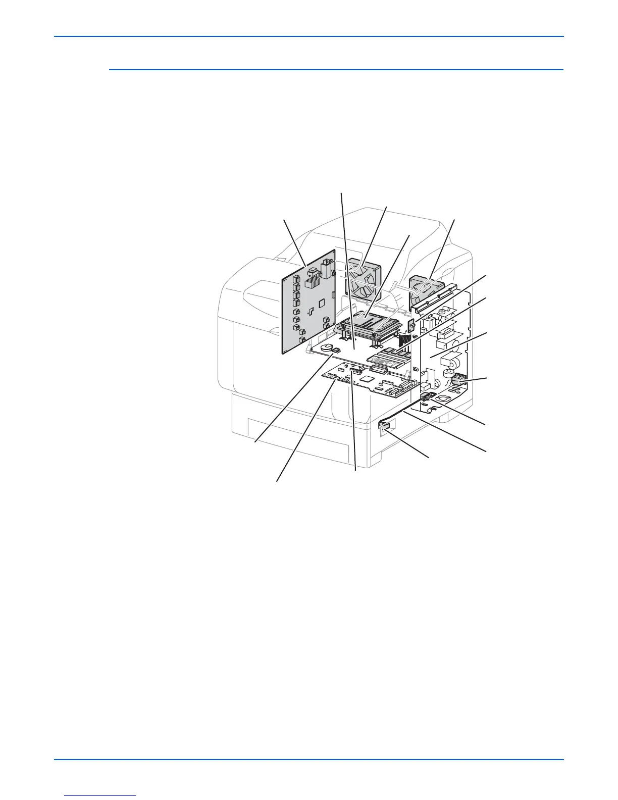
Many of the electrical components used in the 6360 model differ from
those used in 6300/6350 models. The LVPS Fan is only used in 6360
models. Use care when selecting the replacement parent assembly or
component part
■ Image Processor Board
Receives data from the workstation or host, rasterizes the data and
passes it on to the Engine Control Board. The microprocessors on the
Image Processor Board, generate the control signals used by the Engine
Control Board. Also located on the Image Processor Board are the
system NVRAM chip, Memory, and optional Hard Drive.
■ EEPROM Board
Consumable use (Fuser and Imaging Unit NVRAM data) information is
stored and communicated to the Engine Control Board.
■ Rear and LVPS Fans
Remove heat from the printer to prevent over-heating.
■ Power Switch
An actuator and linkage is used to activate the Power Switch located on
the Low-Voltage Power Supply.
■ High-Voltage Power Supply Board (HVPS)
Supplies high-voltage to the Transfer Roller and Imaging Unit.
s6360-065
High Voltage
Power Supply Board
Engine Control Board
Image Processor Board
Low Voltage
Power Supply
Power Switch Actuator
EEPROM Board
Rear Fan
Memory
LVPS Fan
Hard Drive
Engine Control Board
NVRAM
I/P Board
NVRAM
Power Switch Link
Power Switch
AC Switch Harness