8-62 Phaser 6300/6350/6360 Color Laser Printer Service Manual
Service Parts Disassembly
Chute Assembly Out (PL5.3.1)
1. Remove the Top Main Cover (page 8-11).
2. Remove the Front Cover (page 8-12).
3. Remove the Right Front Cover (page 8-19).
4. Remove the Left Front Cover (page 8-19).
5. Remove the Right Side Cover (page 8-14).
6. Remove the Left Side Cover (page 8-15).
7. Remove Tray 1 (MPT) (page 8-42).
8. Remove the Tray 1 (MPT) Cover (page 8-43).
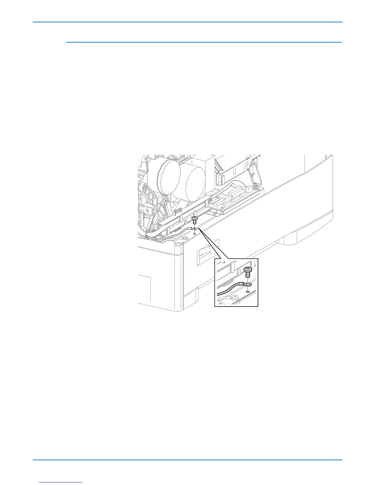
9. Remove the screw (metal with tooth washer, 5 mm) that secures the Tray
1 Feed Solenoid ground wire to the right side of the bottom plate and
remove the wire from the Front Harness Guide.
10. Disconnect P/J710 (Imaging Unit CRUM connector), Developer Drive
Assembly (P/J491), and the Main Drive Assembly (P/J481) and remove
the harnesses from the Front and Rear Cable Guides.
s6360-189