8-108 Phaser 6300/6350/6360 Color Laser Printer Service Manual
Service Parts Disassembly
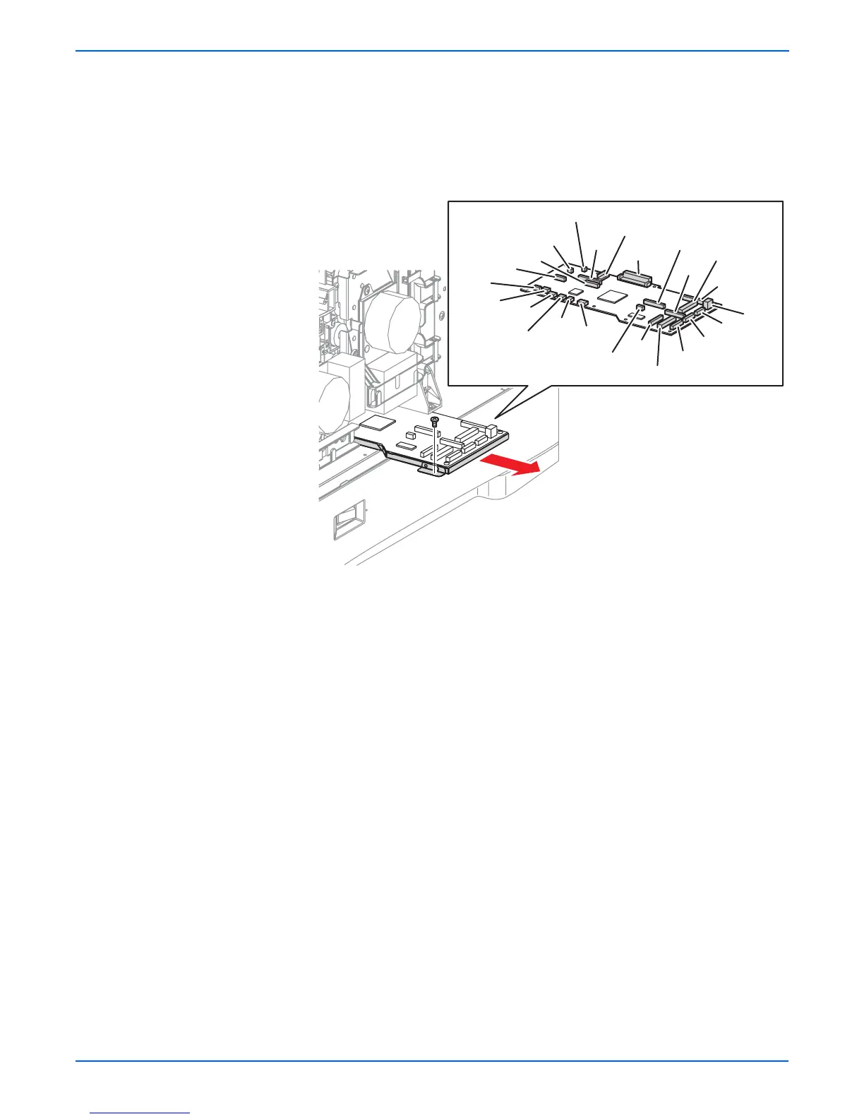
13. Disconnect P/J17, P/J22, P/J47, P/J52, and P/J60 from the Engine
Control Board.
14. Remove the screw (metal, 6 mm) that secures the Engine Control Board
Bracket to the right side of the printer.
15. Lift the right edge of the board slightly and pull the Engine Control Board
out from the printer while removing connections as they are exposed.
Replacement Note
When replacing the Engine Control Board, either replace the NVRAM
device on the new board with the one removed from the old board, or
restore the data saved in Step 1 by using the Restore utility included
in Service Diagnostics.
Also, reconnect P/J15, P/J16, and P/J34 before reinserting the board
into the printer. In addition, connectors P/J13 and P/J36 have an
equal number of Pins. These connectors are keyed differently but use
care to make certain that the proper connection is being made.
Use care re-routing the harnesses after replacing the board.
s6300-220
P52
P48
P13
P47
P17
P60
P16
P24
P154
P34
P191
P19
P18
P21
P30
P22
P51
P36
P61
P14
P311
P31
P15
P20