Home
Philips
Medical Equipment
iE33
Page 150 (Figure 5-11 Placing the Ramp)
Philips iE33 - Figure 5-11 Placing the Ramp
480 pages
Manual
Save Page as PDF
To Next Page
To Next Page
To Previous Page
To Previous Page
Loading...
4535 611 989314730-0047-01iE33 Service Manual
Page 150
CSIP Level 1
Installation: Installation Procedures
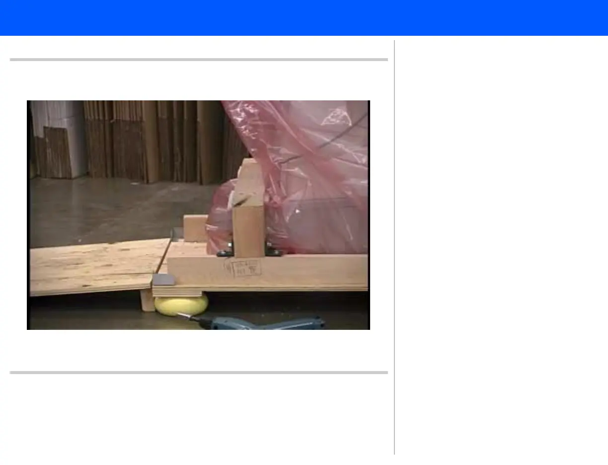
Figur
e 5-11
Placing the Ramp
9.
Place the ramp in fr
ont of the system
with the bev
eled edge facing up.
Return to
Installation Pr
ocedure List
.
149
151
Table of Contents
Main Page
453561198931 Rev A, Service Manual
1
About This Manual
1
Audience
1
Manual Format
1
Conventions in This Manual
1
Service Manual Questions or Comments
2
Customer Assistance
2
Contents
4
1 General Information
33
Introduction
33
Figure 1-1 iE33 Ultrasound System
34
Transducers
35
Physical Description
35
Figure 1-2 Control Panel and Keyboard
37
Figure 1-3 System Peripherals
39
Safety Requirements
40
Supplies and Accessories
41
2 Specifications
42
Introduction
42
Physical Dimensions
42
Imaging Modes
42
Applications
43
Imaging Features
43
System Cart
44
Control Panel and User Interface
45
Stress Echo Protocols
46
Quick Save Feature
47
Image Presentation
47
Cineloop Review
47
Physio
48
System Architecture
48
Display Annotation
49
Transducers
50
Measurements and Analysis
51
Measurement Tools and General Description
51
QLAB Advanced Quantification Plug-in Options
52
Clinical Option Analysis Packages
55
High Q Automatic Doppler Analysis
56
Connectivity
57
Video Monitor
58
Peripheral Devices/Exam Documentation
59
Electrical Power/Video Parameters
59
Environmental Requirements
59
3 Safety
60
Introduction
60
Electrical Safety
60
Mechanical Safety
63
Environmental Safety
65
Equipment Protection
65
Symbols
66
4 Theory of Operation
69
Introduction
69
Operating System
69
System Functional Architecture
69
Signal Flow
70
Physical Structure
71
Figure 4-1 iE33 Physical Structure
71
Power Subsystem
72
Figure 4-2 Power Subsystem Block Diagram
75
Figure 4-3 On/Standby Switch and Power Subsystem Block Diagram
76
Figure 4-4 HV Power Supply Block Diagram
80
Control Subsystem
81
Table 4-1 Host Hard Drive Partitioning
85
Acquisition Subsystem
86
Signal Processing Subsystem
94
Output Power Monitor Theory
96
Acoustic Power and Intensity Manager (APIM)
97
Temperature Monitoring
97
X3-1 Transducer Theory
98
Bus Functions
99
Platform Subsystem Buses
99
Inter-Card Cage Buses
100
Front-End Buses
101
Data Paths
102
Figure 4-5 2D Echo and M-mode Data Path Block Diagram
103
5 Installation
104
Introduction
104
Materials and Equipment
104
Site Inspection
105
Environmental Requirements
105
Table 5-1 System Specifications (Crated/Uncrated)
106
Electrical Power Requirements
107
Image Management Network Requirements
107
System Uncrating
108
Crate Inspection
108
Uncrating Procedure
108
System Inspection
109
Introduction
109
General Inspection
109
System Powerup
110
Peripheral Installations
111
VCRs
111
Table 5-2 Mitsubishi HS-MD3000UA/EA VCR Control Settings
113
Table 5-3 Mitsubishi HS-MD3000U/E and HS-MD3000UA/EA VCR RS-232 Interface Adapter Switch Settings
113
Table 5-4 Mitsubishi HS-MD3000UA/EA VCR Menu Settings
114
Table 5-5 Mitsubishi HS-MD3000U/E and HS-MD3000UA/EA VCR Hidden Menu Control Settings
116
Printers
117
Table 5-6 Sony UPD-23MD Digital Color Printer Driver Settings
119
External Monitor or Other Display Device
121
Connectivity Information
121
Preparation
121
Ethernet Connection
122
Figure 5-1 Ethernet Connection Diagram
123
Figure 5-2 Tech Admin Connectivity Tools
124
Ultrasound System Configuration
125
Adding DICOM Printers or Servers
126
Selecting Devices
127
Verifying Devices
129
DVD Configurations
129
Hard Drive Maintenance
130
Printer and Image Capture Configurations
130
Final Test Procedure
131
Additional Image Adjustments
131
Display Image Quality
131
Loop Frame Rate
132
Print Image Quality
133
Installation Completion
133
Final Inspection
133
System Presentation
134
Final Presentation
137
Connectivity Worksheet
137
Table 5-7 Connectivity Worksheet
138
Installation Checklist
140
Installation Procedures
142
Figure 5-3 Installation Procedure List
142
Uncrating the iE33 Ultrasound System
143
Figure 5-4 Cutting the Plastic Banding
143
Figure 5-5 Removing the Corrugated Cover
144
Figure 5-6 Removing the Braces
145
Figure 5-7 Cutting the Tape on the Seams
146
Figure 5-8 Removing One of the Corrugated Wraps
147
Figure 5-9 Removing the Second Corrugated Wrap
148
Figure 5-10 Removing the Ramp from the Pallet
149
Figure 5-11 Placing the Ramp
150
Figure 5-12 Removing the System Rear Anchor Hardware
151
Figure 5-13 Removing the Ring Connectors
152
Figure 5-14 Removing the Front Hold-Down Brace
153
Figure 5-15 Preparing to Roll the System off the Pallet
154
Figure 5-16 Rolling the System off the Pallet
155
Crating the iE33 Ultrasound System
156
Figure 5-17 Placing the Ramp
156
Figure 5-18 Locking the Right-Rear Caster
157
Figure 5-19 Supporting the Monitor and Arm
158
Figure 5-20 Covering the System with an Anti-Static Bag
159
Figure 5-21 Rolling the System onto the Pallet
160
Figure 5-22 Swiveling the Front Casters
161
Figure 5-23 Installing the Front Hold-Down Brace
162
Figure 5-24 Installing the Control Panel Support
163
Figure 5-25 Installing the Handle Bar Brace
164
Figure 5-26 Installing the Ramp onto the Pallet
165
Figure 5-27 Installing the System Rear Anchor Hardware
166
Figure 5-28 Placing the First Corrugated Wrap
167
Figure 5-29 Placing the Second Corrugated Wrap
168
Figure 5-30 Taping the Seams on the Corrugated Wrap
169
Figure 5-31 Folding the Top System Support Braces
170
Figure 5-32 Placing the Top System Support Braces
171
Figure 5-33 Placing the Monitor Arm Brace
172
Figure 5-34 Placing the Corrugated Cover
173
Figure 5-35 Banding the System Crate
174
Shipping Strap Brackets
175
Figure 5-36 Removing Shipping Strap Brackets
175
Video Monitor Articulation Arm
176
Figure 5-37 Unlocking the Articulation Arm
176
Lower OEM Deck and Strapping (Single OEM)
177
Figure 5-38 Preparing Lower OEM Deck Strapping
177
Figure 5-39 Removing the OEM Tray
178
Figure 5-40 Lower Deck Anchors and Drop Covers
179
Figure 5-41 Installing the Lower Deck Cable Cover
180
Figure 5-42 Placing the VCR on the Lower OEM Deck
181
Figure 5-43 Installing Lower Deck OEM Strapping Over the VCR
182
Figure 5-44 Securing Lower OEM Deck Strapping
183
Figure 5-45 Attaching the Lower OEM Shelf to the Upper OEM Shelf
184
Figure 5-46 Installing Lower OEM Deck Shelf Unit
185
Figure 5-47 Replacing the OEM Tray
186
Upper OEM Deck Shelf and Strapping (Dual OEM)
187
Figure 5-48 Preparing Upper Shelf OEM Deck Strapping
187
Figure 5-49 Removing the Upper OEM Tray
188
Figure 5-50 Placing the Printer on the Upper OEM Shelf
189
Figure 5-51 Strapping the Printer to the Upper OEM Shelf
190
Figure 5-52 Securing the Upper OEM Strapping and Cable Cover
191
Figure 5-53 Installing the Upper OEM Strap Cover
192
6 Performance Tests
193
Introduction
193
Test Equipment and Materials
194
Initial Setup
194
Start Exam
194
2D
195
Color/CPA
196
PW Doppler, CW Doppler, and M-mode
197
Live 3D Echo
197
Connectivity and Review
198
Annotations and Body Markers
199
Measurement and Analysis
200
Voice Recognition
201
Peripherals
201
VCR
201
Printer
202
Performance Test Checklist
203
7 Adjustments
204
Power Supply Voltage Adjustments
204
Video Monitor Articulation Elevation, Tilt, and Swivel Adjustment
204
Figure 7-1 Video Monitor Articulation Arm Buoyancy Adjustment
205
Figure 7-2 Video Monitor Tilt Adjustment
206
Figure 7-3 Video Monitor Swivel Adjustment
207
Video Monitor Adjustments
208
Figure 7-4 Display Tab of the System Settings Setups
209
Video Monitor to System Video Adjustment
210
Touch Screen Calibration
212
Control Panel Lateral Translation Force Adjustment
213
Figure 7-5 Control Panel Lateral Translation Force Adjustment
214
Keyboard Slide Catch Adjustment
215
Figure 7-6 Keyboard Slide Catch Adjustment
216
Control Panel Articulation Adjustments
217
Figure 7-7 Control Panel Articulation Trigger Adjustment
218
Figure 7-8 Control Panel Articulation Base Adjustment
219
8 Preventive Maintenance
220
Introduction
220
Required Tools and Equipment
220
Fan/Air Filters
220
Figure 8-1 Side Fan Filter Removal
221
Figure 8-2 Rear Fan Filter Removal
222
Casters
223
Brake and Swivel-Lock Mechanism
223
Figure 8-3 Brake and Swivel-Lock Pedals
224
Figure 8-4 Underside of Brake and Swivel-lock Assembly
225
Figure 8-5 Swivel-lock Caster Linkage (Right Rear Caster)
226
Control Panel Articulation
227
Figure 8-6 Control Panel Articulation Travel Lock (Side-to-Side Release)
228
Trackball
229
Figure 8-7 Trackball Cleaning
230
Monitor Articulation
231
Video Monitor and Touch Screen
232
Exterior Surfaces
233
Clearing the Patient Directory
233
Operational Test and Paperwork
234
Preventive Maintenance Checklist
235
9 Troubleshooting
237
Introduction
237
Troubleshooting Procedure
237
Power Input Requirements
240
Table 9-1 Power Specifications
242
Power Supply Information
242
Table 9-2 Acquisition Card Cage Voltages
243
Table 9-3 System Power LED Status
245
Temperature Monitoring
245
Table 9-4 PCB Temperature Sensor Information
247
Abnormal On/ Standby LED States
247
System Software Tools
248
Manage Setups
248
Lic Options
248
System Confidence Test
249
Figure 9-1 System Confidence Test Screen
250
Tech Admin
251
Figure 9-2 Tech Admin Functions Screen
252
Channel Walk Test
255
Table 9-5 Channel Walk System Settings
255
FEC Debug Port
256
Table 9-6 FEC Debug Port HyperTerminal Settings
257
UpLink Network Configuration
259
10 Disassembly
260
Introduction
260
Disassembly Procedures
261
Figure 10-1 Disassembly Procedure List (1 of 2)
261
Figure 10-2 Disassembly Procedure List (2 of 2)
262
iE33 System Enclosures
263
Figure 10-3 Upper Front Panel Enclosure
263
Figure 10-4 Lower Front Panel Enclosure
264
Figure 10-5 Top Control Panel Articulation Enclosure
265
Figure 10-6 Handle Enclosures
266
Figure 10-7 Front Pivot Articulation Enclosure
267
Figure 10-8 Control Panel Articulation Arm Beard Enclosure Assembly
268
Figure 10-9 Control Panel Articulation Top Lid Enclosure
269
Figure 10-10 Transducer Holders
270
Figure 10-11 Transducer-Holder Mounts
271
Figure 10-12 Power Supply Cover Enclosure
272
Figure 10-13 Filter Door Cover Enclosure
273
Figure 10-14 Side Panel Enclosures
274
Figure 10-15 Rear Panel Enclosure
275
Figure 10-16 Front Bumper Enclosures
276
Figure 10-17 Rear Side Enclosures
277
Figure 10-18 Rear Disk Bay Enclosure
278
Figure 10-19 Disk Bay Insert Enclosure
279
Figure 10-20 Right Side Column Disk Bay Enclosure
280
Figure 10-21 Left Side Column Disk Bay Enclosure
281
Figure 10-22 Rear Column Disk Bay Enclosure
282
Figure 10-23 Front Column Disk Bay Enclosure
283
Figure 10-24 Front Column Disk Bay Screw Installation Sequence
284
Figure 10-25 Mud Plate Enclosure
285
Figure 10-26 Brake Pedal Extension Covers
286
Touch Screen Assembly
287
Figure 10-27 Touch Screen Bezel
287
Figure 10-28 Touch Screen
288
Figure 10-29 Backlight Inverter Location
289
Fiber-Optic Keyboard Lighting
290
Figure 10-30 Front Touch Screen Bezel
290
Figure 10-31 Touch Screen Overlay
291
Figure 10-32 Control Panel Top Cover
292
Figure 10-33 Lower Front Light Bezel
293
DVD Drive Assembly
294
Figure 10-34 Removing the TEE Probe Tray
294
Figure 10-35 Rear Disk Bay Enclosure
295
Figure 10-36 Disk Bay Insert Enclosure
296
Figure 10-37 Rear Disk Bay Cover
297
Figure 10-38 Disconnecting the DVD Drive Cables
298
Figure 10-39 DVD Drive
299
Speaker Assemblies
300
Figure 10-40 Upper Front Panel Enclosure
300
Figure 10-41 Lower Front Panel Enclosure
301
Figure 10-42 Top Control Panel Articulation Enclosure
302
Figure 10-43 Transducer Holders
303
Figure 10-44 Transducer-Holder Mounts
304
Figure 10-45 Right/Left Side Panel Enclosures
305
Figure 10-46 Speaker Mounting Plate Cable Connector
306
Figure 10-47 Speaker Mounting Plate
307
Acquisition Card Cage and Frontplane
308
Figure 10-48 Upper Front Panel Enclosure
308
Figure 10-49 Lower Front Panel Enclosure
309
Figure 10-50 Top Control Panel Articulation Enclosure
310
Figure 10-51 Control Panel Articulation Arm Beard Enclosure Assembly
311
Figure 10-52 Rotating the Front Panel Hanger Brackets
312
Figure 10-53 Frontplane Warning Label
313
Figure 10-54 Frontplane Assembly Screws
314
Figure 10-55 Frontplane Assembly
315
Figure 10-56 Uncabling the Frontplane Assembly
316
Figure 10-57 Reinstalling the Frontplane Assembly
317
Acquisition Card Cage, PCBs, and Scanhead Select
318
Figure 10-58 Front Column Disk Bay Enclosure
318
Figure 10-59 Rotating the PCB Retainer Brackets
319
Figure 10-60 Acquisition Card Cage PCBs
320
Figure 10-61 Releasing the Captive Screws
321
Figure 10-62 Scanhead Select Module
322
System Power Cord (100/120 V and 230 V)
323
Figure 10-63 System Power Cord Warnings
323
Figure 10-64 Rear Panel Enclosure
324
Figure 10-65 Installing the 100/120-V Power Cord
325
Figure 10-66 Installing the 230-V Power Cord
326
AC Tray
327
Figure 10-67 Rear Panel Enclosure
327
Figure 10-68 AC Tray Screws
328
Figure 10-69 AC Tray
329
Acquisition Power Supply and HV Switcher
330
Figure 10-70 Power Supply Cover Enclosure
330
Figure 10-71 Acquisition Power Supply
331
Figure 10-72 HV Switcher
332
Filter Tray, Platform Power Supply, and Battery Tray
333
Figure 10-73 Filter Door Cover Enclosure
333
Figure 10-74 Filter Tray
334
Figure 10-75 Platform Power Supply
335
Figure 10-76 Battery Tray
336
Filter Tray Cooling Fans
337
Figure 10-77 Filter Door Cover Enclosure
337
Figure 10-78 Filter Tray
338
Figure 10-79 Filter Tray Cooling Fans
339
Rear Cooling Fans
340
Figure 10-80 Rear Panel Enclosure
340
Figure 10-81 Rear Cooling Fan Assemblies
341
Caster, Left Rear (Free-Swivel)
342
Figure 10-82 Left Rear Caster
342
Figure 10-83 Installing the Left Rear Caster
343
11 Cabling
344
Introduction
344
Cable Part Numbers
344
Cable Lists
345
Table 11-1 iE33 System Signal Interconnect Cables
345
Table 11-2 iE33 System Power Distribution Cables
347
Table 11-3 iE33 System OEM Signal Interconnect Cables
349
Table 11-4 iE33 System Test Cables
350
System Connector Illustrations
351
Figure 11-1 Front Panel Connector Locations (Frontplane Assembly)
351
Figure 11-2 Scanhead Select (SHSEL) Connector Locations
352
Figure 11-3 Rear Interface Panel Connector Locations (AVIO-RIP)
353
Figure 11-4 Rear Interface Panel Dual USB Connector Configuration
354
Figure 11-5 User USB Connector Location (Rear of Disk Bay Housing)
355
Figure 11-6 AC Power Receptacle (AC Tray) Side View
356
Figure 11-7 Terminal Block and Relay Wire Connection Diagram (AC Tray)
357
Figure 11-8 J32 Feature Connector (Host/SIP Motherboard)
358
OEM Cabling Diagrams
359
Figure 11-9 HS-MD3000UA/EA Mitsubishi VCR Cabling Diagram
359
Figure 11-10 UP-D895MD Sony Digital Black-and-White Printer Cabling Diagram
360
Figure 11-11 UPD-23MD Sony Digital Color Printer Cabling Diagram
361
Test Cabling
362
Figure 11-12 Acquisition Frontplane to Laptop Serial Port Cable Assembly (P/N 453561170191)
362
Table 11-5 Acquisition Frontplane to Laptop Serial Port Cable Assembly (P/N 453561170191)
363
Figure 11-13 Acquisition Frontplane to Laptop Serial Port Connection Diagram
364
Figure 11-14 iE33 Ultrasound System Signal Interconnect Diagram
365
Figure 11-15 iE33 Ultrasound System AC/DC Power Distribution Diagram
366
12 Change History
367
1.0.0.399
367
13 Configuration
368
Compatibility
368
Primary PCB Locations
368
Figure 13-1 Acquisition Card Cage PCB Names and Locations
369
Supported Media
370
Table 13-1 Types of Media Supported in the DVD Drive
370
14 Parts
371
Introduction
371
Parts Ordering Information
372
How to Find a Part Number
373
Illustrations
376
Figure 14-1 iE33 Ultrasound System Parts Locator Map (Front and Rear Ends)
376
Figure 14-2 iE33 Ultrasound System Parts Locator Map (Left and Right Sides)
377
Figure 14-3 Video Monitor, Flat-Panel
378
Figure 14-4 Video Monitor, Flat-Panel (Front Enclosure)
379
Figure 14-5 Video Monitor, Flat-Panel (Rear Enclosure)
380
Figure 14-6 Video Monitor, Flat-Panel (Cables)
381
Figure 14-7 Video Monitor Articulation Arm
382
Figure 14-8 Video Monitor Articulation Arm (Upper)
383
Figure 14-9 Video Monitor Articulation Arm (Lower)
384
Figure 14-10 Video Monitor Articulation Arm (Latch Mechanism)
385
Figure 14-11 Video Monitor Articulation Arm (Elbow Assembly)
386
Figure 14-12 DVD Drive Housing
387
Figure 14-13 DVD Drive Housing (Covers and Cables)
388
Figure 14-14 DVD Drive Housing (Power On/Standby Switch)
389
Figure 14-15 DVD Drive Housing (Microphone Mount)
390
Figure 14-16 DVD Drive Housing (DVD Drive Assembly)
391
Figure 14-17 USB Hub (Printer)
392
Figure 14-18 Control Panel
393
Figure 14-19 Control Panel (Control Knobs and Transducer Holder)
394
Figure 14-20 Control Panel (Cables)
395
Figure 14-21 Control Panel (Lower Housing)
396
Figure 14-22 Control Panel (Keyboard)
397
Figure 14-23 System Enclosures (Right Front View)
398
Figure 14-24 System Enclosures (Left Rear View)
399
Figure 14-25 Rear Enclosure Assembly
400
Figure 14-26 Transducer Holder Assemblies
401
Figure 14-27 Speaker Boxes
402
Figure 14-28 Speaker Box Assembly, Right
403
Figure 14-29 Speaker Box Assembly, Left
404
Figure 14-30 OEM Deck
405
Figure 14-31 No OEM Configuration (OEM Deck)
406
Figure 14-32 Single OEM Configuration (OEM Deck)
407
Figure 14-33 Dual OEM Configuration (OEM Deck)
408
Figure 14-34 TEE Probe Tray
409
Figure 14-35 Acquisition Card Cage
410
Figure 14-36 Acquisition Card Cage (Shields and Panels)
411
Figure 14-37 Acquisition Card Cage (Frontplane Assembly)
412
Figure 14-38 Acquisition Card Cage (Card Cage Detail)
413
Figure 14-39 Power Supply Enclosure
414
Figure 14-40 System Brake and Steering Lock
415
Figure 14-41 System Brake/Steering Lock Detail
416
Figure 14-42 Acquisition Power Supply
417
Figure 14-43 Acquisition Power Supply Detail
418
Figure 14-44 Filter Tray (Cooling Fans)
419
Figure 14-45 Filter Tray detail
420
Figure 14-46 Platform Power Supply
421
Figure 14-47 Platform Power Supply Detail
422
Figure 14-48 Battery Tray and HV Switcher
423
Figure 14-49 Battery Tray Detail
424
Figure 14-50 HV Switcher Detail
425
Figure 14-51 AC Tray
426
Figure 14-52 AC Tray Detail
427
Figure 14-53 AC Tray Power Receptacle/Switch
428
Figure 14-54 Rear Cooling Fans and Shipping Brackets
429
Figure 14-55 Casters
430
Figure 14-56 Front Caster (Brake)
431
Figure 14-57 Rear Caster (Swivel)
432
Figure 14-58 System Labeling, Side of System
433
Figure 14-59 System Labeling, Front of System (1 of 4)
434
Figure 14-60 System Labeling, Front of System (2 of 4)
435
Figure 14-61 System Labeling, Front of System (3 of 4)
436
Figure 14-62 System Labeling, Front of System (4 of 4)
437
Figure 14-63 System Labeling, Rear of System (1 of 3)
438
Figure 14-64 System Labeling, Rear of System (2 of 3)
439
Figure 14-65 System Labeling, Rear of System (3 of 3)
440
Parts List
441
Table 14-1 iE33 Ultrasound System Parts List
441
Accessories Parts List
459
Table 14-2 iE33 Ultrasound System Accessories Parts List (Not Illustrated)
459
Peripherals Parts List
460
Table 14-3 Peripherals and Applicable Cables
460
15 Transducers
461
Compatibility
461
Table 15-1 Transducer Information
461
Transducer Specfications
462
Table 15-2 X3-1 Matrix Transducer
463
Table 15-3 S5-1 Sector Array Transducer
464
Table 15-4 S7-2omni Transducer
465
Table 15-5 S8-3 Sector Array Transducer
466
Table 15-6 L8-4 Linear Array Transducer
467
Table 15-7 L11-3 Linear Array Transducer
468
Table 15-8 D2cwc Transducer
469
Table 15-9 D5cwc Transducer
469
16 System Administration
470
System Admin
470
Displaying the System Software Level
470
Recordable Media
470
Formatting a Blank DVD
471
Copying Settings to a DVD
471
Figure 16-1 Manage Setups Tab
473
Importing Settings from a DVD
474
Exporting User Logons
475
Importing User Logons
476
Exporting Images to DVD
476
Saving User Settings
477
Restoring User Settings
478
Exporting Registered Users
478
Hard Drive Maintenance
479
Other manuals for Philips iE33
User Manual
364 pages
Related product manuals
Philips iU22
342 pages
Philips IntelliVue MP5
362 pages
Philips IntelliVue MP20
18 pages
Philips IntelliVue MP70
278 pages
Philips IntelliVue MX800
460 pages
Philips InnoSpire Essence
111 pages
Philips InnoSpire Elegance
93 pages
IntelliVue MX800IntelliVue MP2
316 pages
Philips BiPAP
24 pages
Philips HeartStart FR2+
100 pages
Philips REMstar Auto A-Flex
24 pages
Philips HeartStart FR3 Series
24 pages