4535 611 98931 iE33 Service Manual Page 75
CSIP Level 1 Theory of Operation: Physical Structure
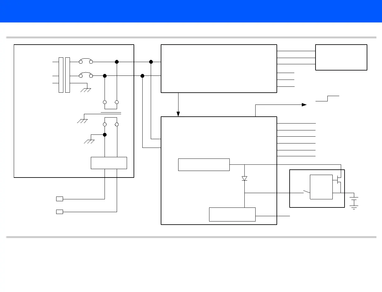
Figure 4-2 Power Subsystem Block Diagram
+12 V standby
+5 V standby
Logic
+5 VSB (To ATX Motherboard)
+12 VSB
Line_OK_n
-12
+12
-5
+5
+3.3
+15
-5.3
+5.3
+3.5
-15
+48
Acq_DC_OK_n
OK
Acq_DC_OK_n
DC_OK_Out
System battery charger
6 V sealed
lead acid
battery
OEM AC relay
L
N
G
100, 120 or
220 - 240
Vac
Main circuit breaker 15 A
Input receptacle/EMI filter
To VCR
To printer
1
2
43
See Figure 4-1
On/Standby Switch and Power
Acquisition Power Supply Module
HV
Switcher
AC Tray
Blue text are links to additional information.