4535 611 989314730-0047-01iE33 Service Manual Page 281
CSIP Level 1 Disassembly: Disassembly Procedures
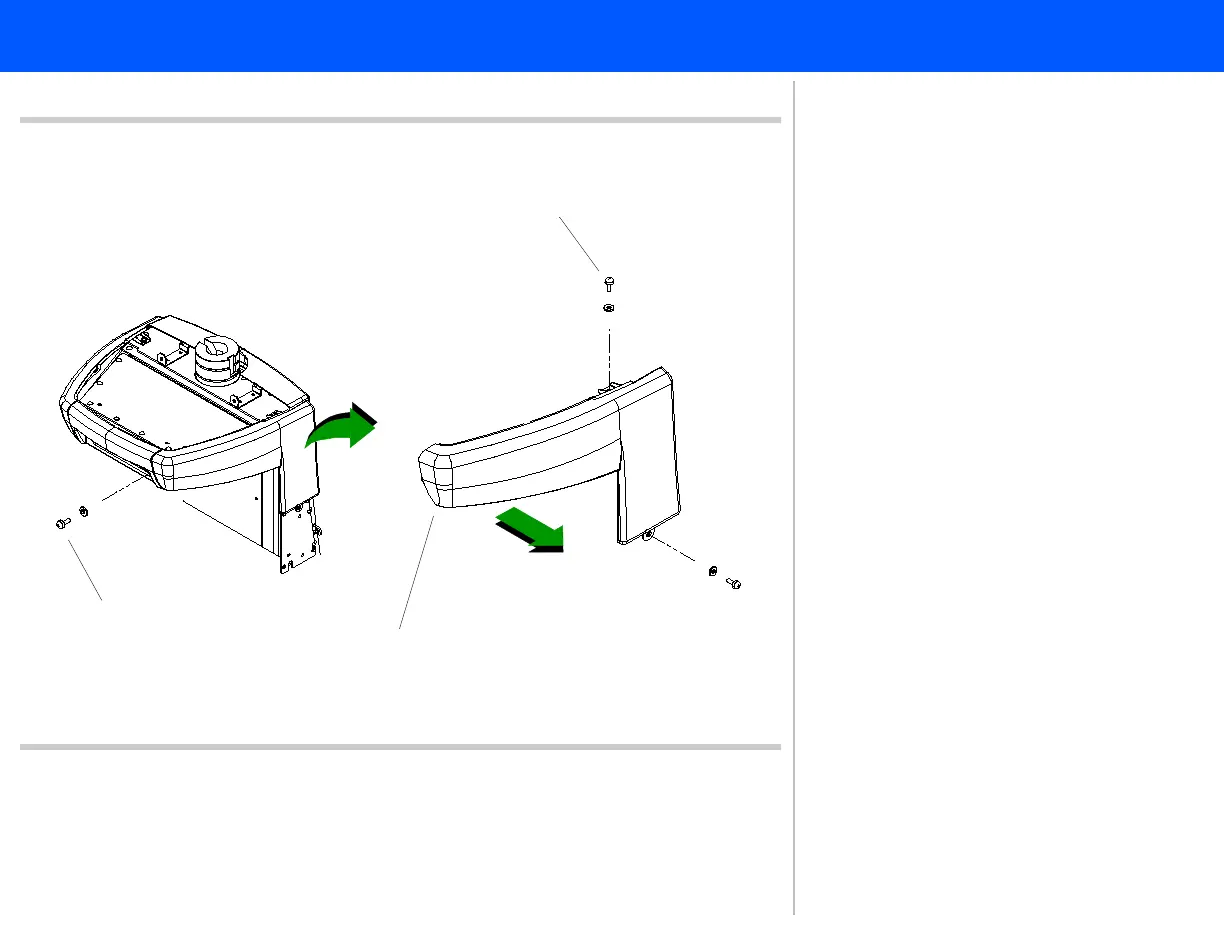
Figure 10-21 Left Side Column Disk Bay Enclosure
Panhead screws (2 plcs)
Panhead screw
Screw bracket (behind enclosure)
42
43
41
41. Remove the panhead screw on the
left side of the rear disk bay enclo-
sure. This screw also secures the left
side column disk bay enclosure
through a screw bracket.
42. Remove the two remaining panhead
screws securing the left side column
disk bay enclosure.
43. Grasp both sides of the enclosure
and slide it straight out from the sys-
tem.
Return to .Disassembly Procedure List
(1 of 2)