4535 611 989314730-0047-01iE33 Service Manual Page 284
CSIP Level 1 Disassembly: Disassembly Procedures
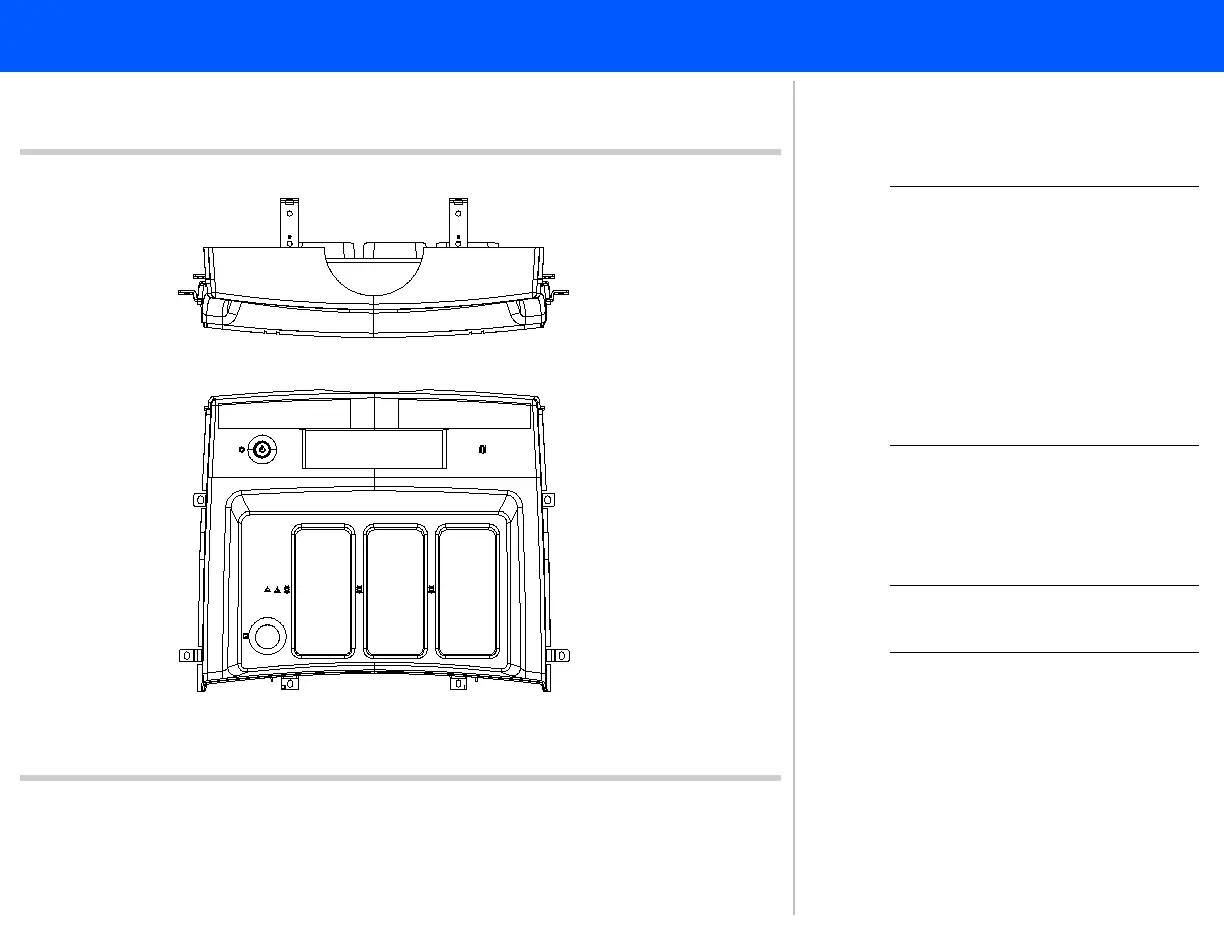
Figure 10-24 Front Column Disk Bay Screw Installation
Sequence
12
3
3
3
3
44
44
Top view
Front view
47
NOTE The front disk bay enclosure
screws must be installed in a
specific sequence to ensure
that it is aligned properly. If this
enclosure is not installed cor-
rectly, it is impossible to install
or align the remaining enclo-
sures.
47. To reinstall the front disk bay enclo-
sure use the 10 panhead screws and
follow the sequence in Figure 10-24.
NOTE Reinstall the system enclo-
sures in the reverse order..
Return to .Disassembly Procedure List
(1 of 2)