4535 611 98931 iE33 Service Manual Page 76
CSIP Level 1 Theory of Operation: Physical Structure
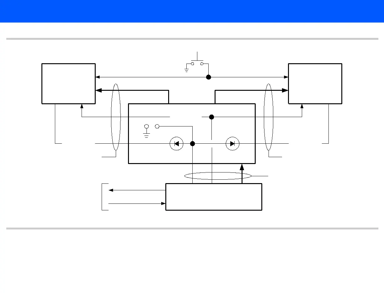
Figure 4-3 On/Standby Switch and Power Subsystem Block Diagram
Platform Power Supply Module
Platform Power Supply
• Provides +3.3 Vdc, ±5.0 Vdc, ±12 Vdc, +12 VSB, and +5 VSB. The +12 VSB is used as a
source for the +5 VSB regulator and a source for the battery charger, located on the
+/-12, +5, -5, +3.3, +5VSB
Motherboard 1
HOST
Motherboard 2
SIP
Platform Power Supply
Custom 600 W
EPS12 V
PWR_OK
PS_ON#_1 PS_ON#_2
PS_ON#
PS_ON_n_ACQ
ACQ_DC_OK_n
Acquisition
Power Supply
On/Standby
DC-5
Power Distribution Board
JP2
453561182431
453561182651
453561182601