4535 611 989314730-0047-01iE33 Service Manual Page 343
CSIP Level 1 Disassembly: Disassembly Procedures
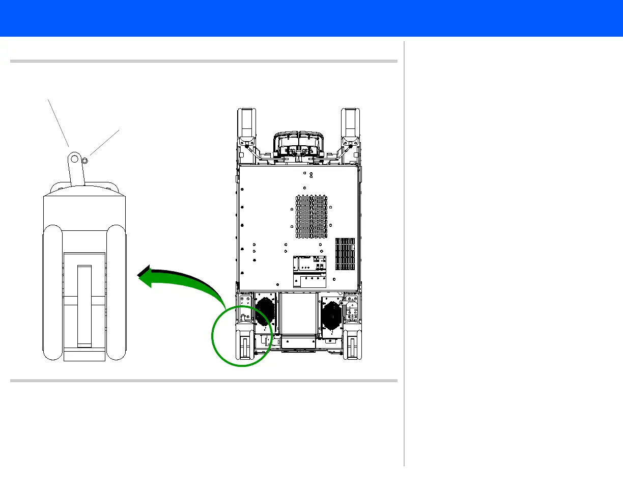
Figure 10-83 Installing the Left Rear Caster
Front of system cart
Bottom view of
system cart
Standoff pin
Linkage lever (outboard side of pin)
Left rear caster
2
3
4
2. To install the left rear caster assem-
bly, ensure that the linkage lever is
pointing toward the front of the sys-
tem cart.
3. Orient the linkage lever on the out-
board side of the standoff pin.
4. Secure the caster to the cart rail
with the four hexhead bolts.
Return to .Disassembly Procedure List
(2 of 2)