4535 611 98931 iE33 Service Manual Page 80
CSIP Level 1 Theory of Operation: Physical Structure
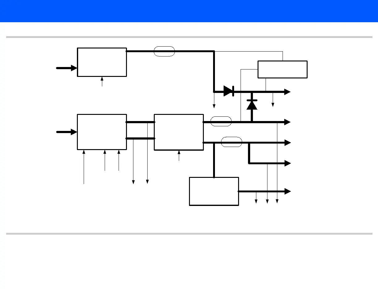
Figure 4-4 HV Power Supply Block Diagram
HV switcher
(0 -125 V each rail)
AIM+
HV regulator
(0 -120 V each rail)
HV_CTRL1+/-
HVIN voltage
monitors
HV_DISABLE_N
HVIN+
HVIN-
From
acquisition PS
ACQ_48 V
AIM+ HV regulator
(0 -120 V each rail)
HV_CTRL
HV+
HV-
HV current monitors
HVB, HV voltage
monitors
HV+ to
Channel board
pulsers
HV- to
Channel board
pulsers
HV- to
transducer
HVB to
transducer
HV+/- used for most transducers.
HVB used for some transducers.
LV Provides a lower noise power supply to the matrix array pulsers for CW operation.
AIM+ LV regulator
0 - 12 V
From
acquisition PS
ACQ_+15V
AIM+ XHV +active
pulldown circuit
LV_CTRL
LV
LV current monitor
LV voltage
monitor
XHV+ voltage
monitor
XHV+ to transducer
See Figure 4-2