4535 611 989314730-0047-01iE33 Service Manual Page 296
CSIP Level 1 Disassembly: Disassembly Procedures
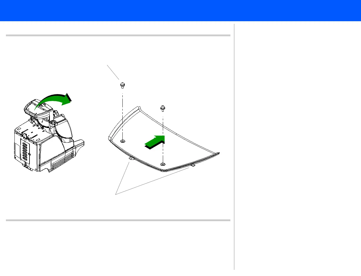
Figure 10-36 Disk Bay Insert Enclosure
Panhead screws (2 plcs)
Tabs (3 plcs)
5
6
5. Remove the two panhead screws
securing the disk bay insert enclo-
sure.
6. Slide the enclosure toward the front
of the system, until the tabs are clear
of the column enclosures, and set it
aside.
Return to .Disassembly Procedure List
(1 of 2)