4535 611 98931 iE33 Service Manual Page 366
CSIP Level 1 Cabling: Cabling Diagrams
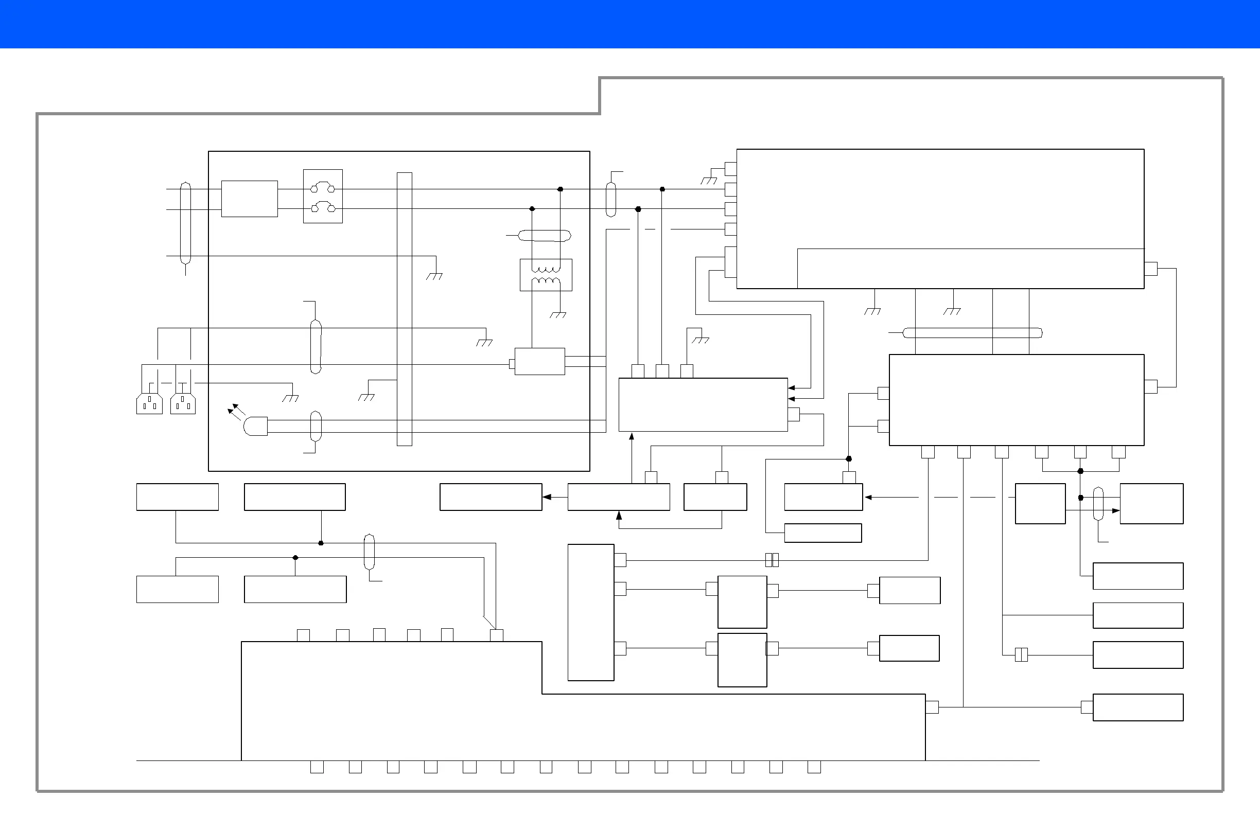
Figure 11-15 iE33 Ultrasound System AC/DC Power Distribution Diagram
Filter
OEM relay
15A Circuit breaker
3
4
1
2
3
Terminal block
Black
White
Green
6 N.C.
AC Tray
7
8
9
Black
White
Green
OEM AC input
voltage
4
5
LED
Red
Black
100,120,230,240
Vac input from
wall outlet
2
1
15
OEM
transformer
3 +
4 -
Platform Power Supply
+12Vdc GND +5Vdc +3.3VdcGND
Power Supply Breakout Board
Power Distribution Board
+5Vdc,+3.3Vdc
platform sense
lines
BB1
BB2
BB6
BB7BB5 BB3 BB4A BB4B
Bus bars
SIP Motherboard
Acquisition
Power Supply
HV switcherAcquisition Frontplane
Channel boards (X4),
AIM+, front-end
P8
Print
STAT
P9
B/W
OUT
P10
SVID
OUT
P11
C
OUT
P12
DUAL
SVID IN
P13
C
IN
P14
EXT
P15
VID
MON
P16
VCR
IN
P17
VCR
OUT
P18
MIC
P19
DUAL
USB
P20
DUAL
USB
P21 E-
NET
P1
E-NET
P2
HOST
USB
AUDIO
P3
SPKRS
P4
AVIO-
CAD
P5
AGP
VIDEO
P6
P&A FANS
BATTERY
BATTERY
TEMP
P7
I BUTTON
+5v
SW-BATT
+12V SB, -12V, +12V
Video monitor
System rear panelSystem rear panel
Host
Motherboard
Host hard drive
DVD drive
AVIO - RIP
Acquisition Card Cage
fans
Platform Card
Cage fans
Battery Battery temp
+3.65 Vdc, +5.35 Vdc,
-5.35 Vdc acquisition
sense lines
+/-15Vdc
+48Vdc
ON/STBY
switch
PS on acquisition
+/- HV, CNTRL
BB8
AC_DC_OK
SIP hard drives
Control
Panel
Module
P507
Touch screen
i Button
Control
Panel
Connector
Board
P8
Control
Panel
Connector
Board
Touch screen
453561179291
453561182591
453561182371
453561182571
453561182361
453561182381
453561158551
453561153492
453561182431
453561182651
453561182601
453561179872
453561153712
453561179301
453561153673
2265-0274-01
453561164201
453561157002
2275-0388-01
453561182501
453561157002
453561182501