Phaser 6500/WorkCentre 6505 Service Manual Xerox Internal Use Only 8-105
Service Parts Disassembly
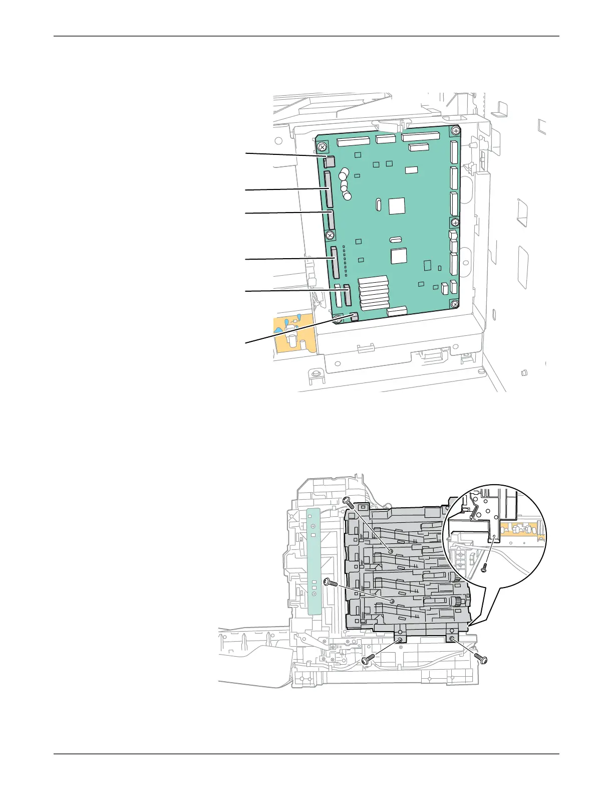
16. Disconnect 7 connectors (P/J14, 15, 17, 18, 19, 29, 31) on the MCU Board.
17. Release all harnesses from the top and bottom guides on the Dispenser
Assembly.
18. Remove four screws (silver, tap, 8mm) that secure the Dispense Assembly to
the chassis.
19. Remove the screw (silver, M4, 6mm) at the rear side of the Dispense Assembly.
s6500-283
P/J15
P/J14
P/J17
P/J31
P/J18
P/J29
s6500-281
 Loading...