Epson Stylus Pro 4900/Epson Stylus Pro 4910 Revision A
DISASSEMBLY & ASSEMBLY Disassembly Flowchart 115
Confidential
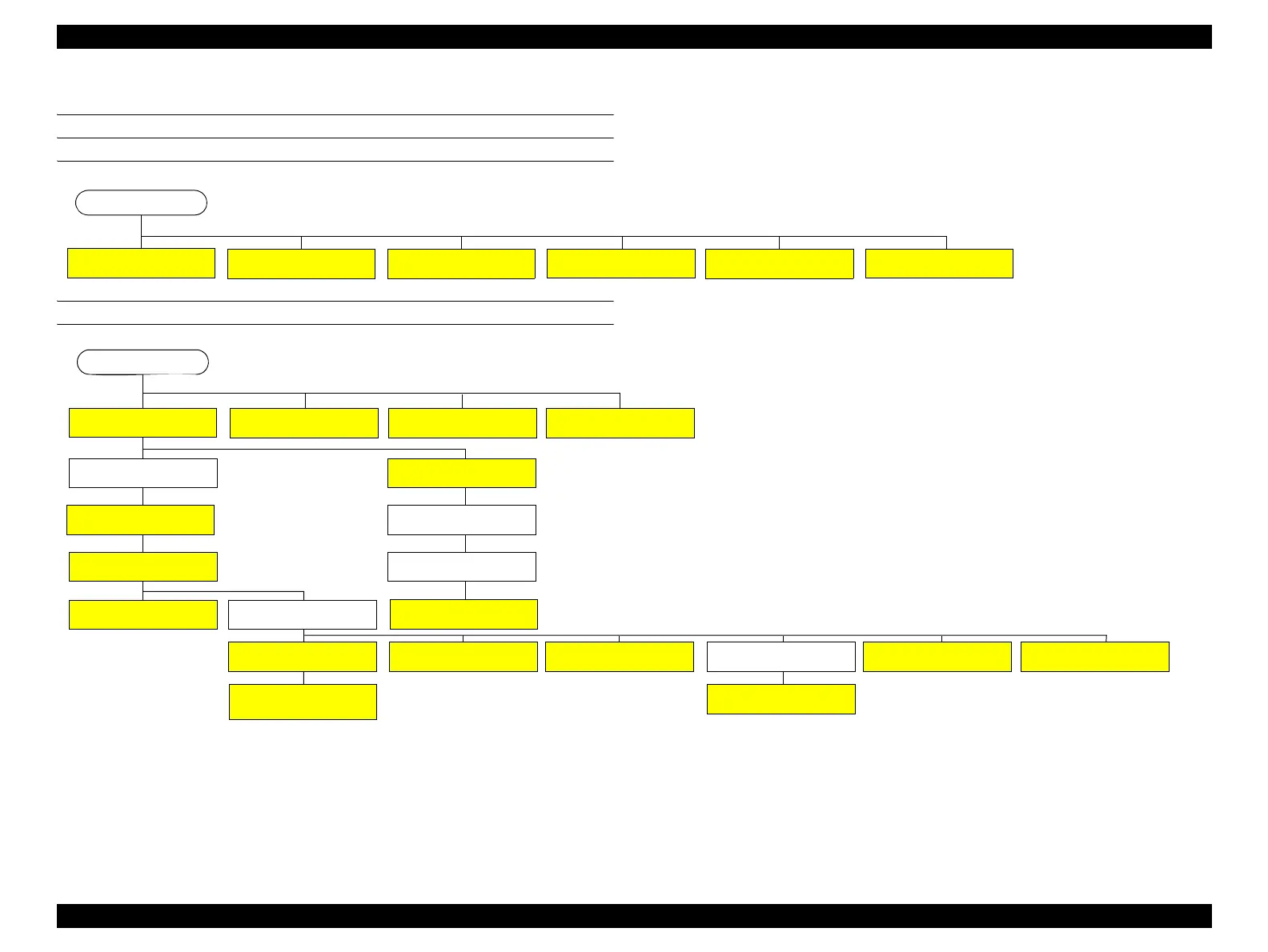
3.3 Disassembly Flowchart
CONSUMABLES/ACCESSORIES
HOUSING
See “3.4.1.1 Unlocking the CR
Unit (p124)”
Start
See “3.4.1.4 Cutter Replacement
(p127)”
See “3.4.1.5 Maintenance box 1
(p128)”
See “3.4.1.6 Maintenance Box2
(p129)”
See “3.4.1.7 Ink Cartridge
Replacement (p130)”
See “3.4.1.9 Mounter (p132)”
See “3.4.2.8 Front Cover (p142)”
See “3.4.2.5 Right Upper Cover
(p138)”
See “3.4.2.15 CR Cover (p149)”
Start
See “3.4.2.6 Right Cover (p139)”
See “3.4.2.4 Left Cover (p137)”
See “3.4.2.11 Rear Unit (p145)”
See “3.4.2.5 Right Upper Cover
(p138)”
See “3.4.2.4 Left Cover (p137)”
See “3.4.2.7 Left IC Cover Frame/
Right IC Cover Frame/ Left IC
Sensor/Right IC Sensor (p140) ”
See “3.4.2.3 Control Panel Cover
(p136)”
See “3.4.2.9 Front Cover Sensor
(p143)”
See “3.4.2.2 Printer Cover Sensor
(p134)”
See “3.4.2.1 Printer Cover (p133)”
See “3.4.2.10 Rear Cover (p144)”
See “3.4.2.11 Rear Unit (p145)”
See “3.4.2.10 Rear Cover (p144)”
See “3.4.2.14 Media Eject Cover
(p148)”
See “3.4.2.10 Rear Cover (p144)”
See “3.4.2.13 Board Tray (p147)”
See “3.4.2.12 Rear Unit Sensor
(p146)”
See “3.4.2.16 Mid-Right Cover/
Mid-Left Cover (p150)”
 Loading...


