Epson Stylus Pro 4900/Epson Stylus Pro 4910 Revision A
DISASSEMBLY & ASSEMBLY Disassembly and Assembly Procedure 276
Confidential
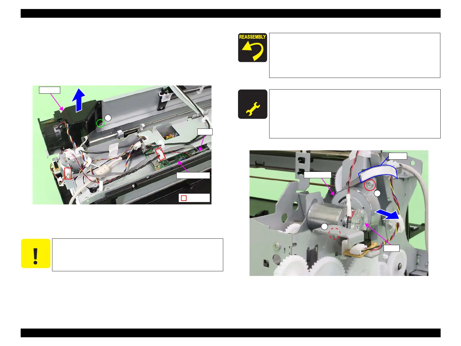
10. Disconnect the connector (CN19) from the Main-C Board.
11. Release the harness from the two clamps.
12. Remove the screw that secures the fan duct.
C) Silver, Phillips, Bind P-tite M3x8: one piece
13. Remove the fan duct.
Figure 3-220. Removing the fan duct
14. Remove the two screws that secure the CR Motor.
D) Silver, Phillips, Bind machine screw M3x6: two pieces
15. Remove the CR Motor.
Figure 3-221. Removing the CR Motor
C A U T I O N
In the next step, be careful not to damage the scale of the encoder
for paper pressing motor.
CN19
Clamp
C
Fan duct
Main-C Board
When installing the CR Motor, be careful of the installation
direction referring to Figure 3-221. Make sure that the harness
is routed as shown in the figure.
When the CR Motor is replaced with a new one, attach the tape
for protecting the harness from the frame to the same position
referring to Figure 3-221.
A D J U S T M E N T
R E Q U I R E D
Be sure to refer to Chapter 4 “Adjustment” (see p277) and perform
specified adjustments after replacing or removing the CR Motor.
<Adjustment items>
1. Counter Reset (Spectroproofer CR Motor Counter)
2. Spectroproofer Movement Check
3. Spectroproofer Measurement Precision Check
D
D
CR Motor
Tape
Scale
 Loading...


