Epson Stylus Pro 4900/Epson Stylus Pro 4910 Revision A
DISASSEMBLY & ASSEMBLY Disassembly and Assembly Procedure 153
Confidential
6. Disconnect all connectors and FFCs on the Main Board.
Figure 3-56. Disconnecting the connectors and FFCs
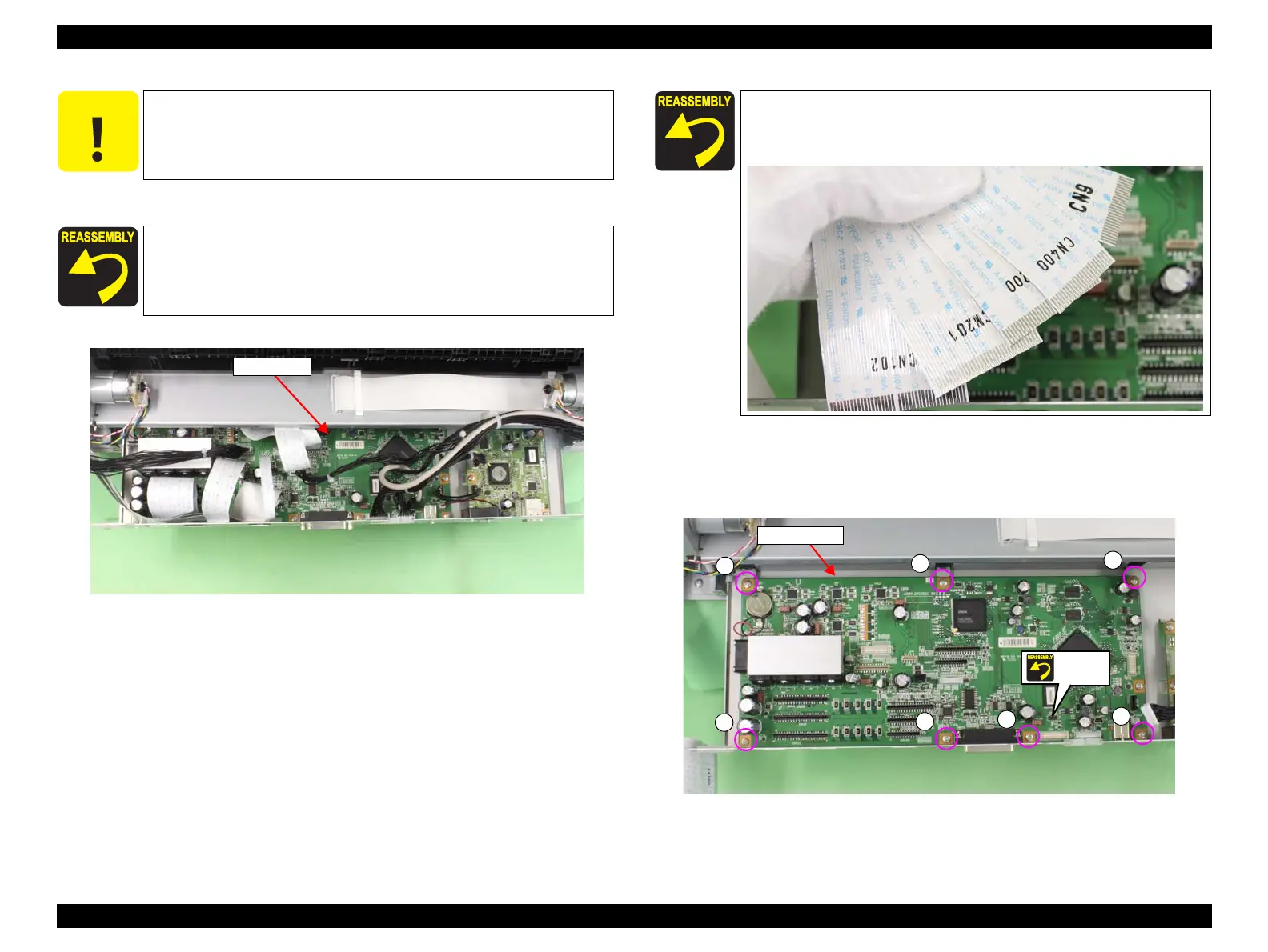
7. Remove the seven screws that secure the Main Board.
A) Silver, Phillips, Bind machine screw M3x6: seven pieces
8. Remove the Main Board.
Figure 3-57. Removing the Main Board
C A U T I O N
Be extremely careful not to insert FFCs at an angle in connectors.
Doing so may cause serious damage to the terminals inside the
connectors, and it can lead to big trouble of the circuit components.
The connector shown in Figure 3-57 is not used.
When installing the Main Board, be sure to refer to Chapter 6
“Appendix” (see p432) and connect the connectors correctly.
Main Board
The connector number that corresponds to the FFC is written on its
surface as shown below. Make sure to connect the FFCs to their
correct connectors according to the numbers.
A
A
A
A
A
A
A
Main Board
Unused
 Loading...


