Epson Stylus Pro 4900/Epson Stylus Pro 4910 Revision A
DISASSEMBLY & ASSEMBLY Disassembly and Assembly Procedure 268
Confidential
3.4.12.4 Drying Fan
1. Remove the Color Measurement Device. (p255)
2. Remove the Mounter. (p132)
3. Remove the Upper Cover. (p257)
4. Remove the I/F Cover. (p258)
5. Remove the Left Cover. (p260)
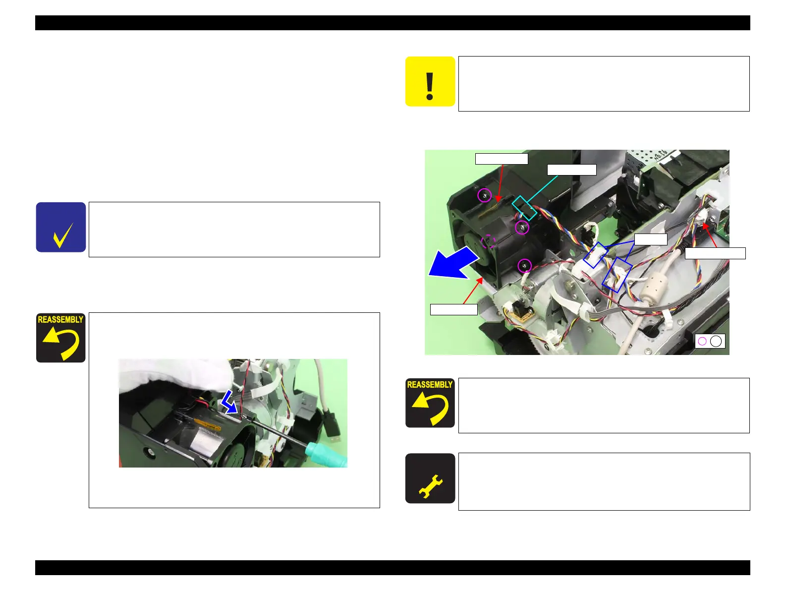
6. Disconnect the relay connector.
7. Release the harness from the clamp and the cable guide.
8. Remove the four screws that secure the Drying Fan.
A) Silver, Phillips, Bind P-tite M2.6x12 (bit: No.1): four pieces
9. Remove the Drying Fan.
Figure 3-210. Removing the Drying Fan
C H E C K
P O I N T
When removing the screws in the next step, use a screwdriver
whose shaft is 3.5 cm or longer.
When securing the Drying Fan with the screws, first insert the
screwdriver into the hole in front of the Drying Fan, and then
set the screw to the driver.
If it is difficult to secure the Drying Fan with the screws, remove
the Rear Cover, and then secure with the screws. (Step 8 to Step 9
in
“3.4.12.8 CR Motor” (P. 275)
)
C A U T I O N
When removing the Drying Fan in the next step, be careful not to
damage the Thermistor.
Make sure to route the harness correctly as shown in Figure 3-209.
A D J U S T M E N T
R E Q U I R E D
Be sure to refer to Chapter 4 “Adjustment” (see p277) and perform
specified adjustment after replacing or removing the Drying Fan.
<Adjustment item>
Spectroproofer Movement Check
Relay connector
Clamps
Cable guide
A
Drying Fan
Thermistor
 Loading...


