Epson Stylus Pro 4900/Epson Stylus Pro 4910 Revision A
DISASSEMBLY & ASSEMBLY Disassembly and Assembly Procedure 164
Confidential
3.4.3.8 SUB-D Board
1. Remove the Right Roll Cover. (p151)
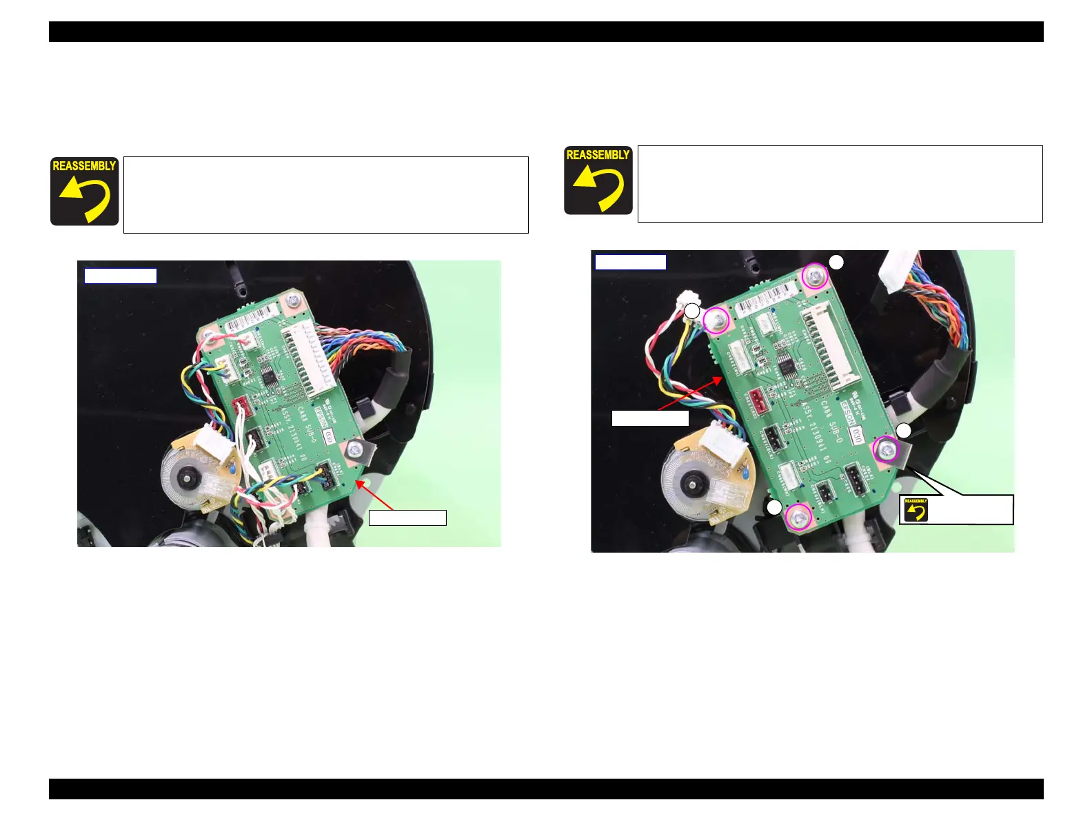
2. Disconnect all the connectors and FFCs on the SUB-D Board.
Figure 3-71. Disconnecting the connectors
3. Remove the four screws that secure the SUB-D Board, and remove the SUB-D
Board.
A) Silver, Phillips, Bind machine screw M3x6: four pieces
Figure 3-72. Removing the SUB-D Board
When installing the SUB-D Board, be sure to refer to Chapter 6
“Appendix” (see p432) and connect the connectors correctly.
SUB-D Board
- Right side -
Secure the SUB-D Board together with the grounding plate using
the same screw shown in the figure.
SUB-D Board
- Right side -
A
A
A
A
Screw together
 Loading...


