Epson Stylus Pro 4900/Epson Stylus Pro 4910 Revision A
DISASSEMBLY & ASSEMBLY Disassembly and Assembly Procedure 219
Confidential
3.4.7.3 ATC Motor Assy
1. Remove the Right Roll Cover. (p151)
2. Remove the SUB-D Board. (p164)
3. Remove the “HOLDER,ROLLER,RIGHT”. (Step 3 to Step 8 in “3.4.7.2 Roll
Lock Sensor” (P. 217))
4. Release the harnesses from the hooks.
5. Remove the three screws that secure the Motor Assy.
A) Silver, Phillips, Round Washer Head S-tite M3x6: three pieces
6. Remove the Motor Assy.
7. Disconnect the connector from the ATC Motor Assy.
Figure 3-149. Removing the Motor Assy
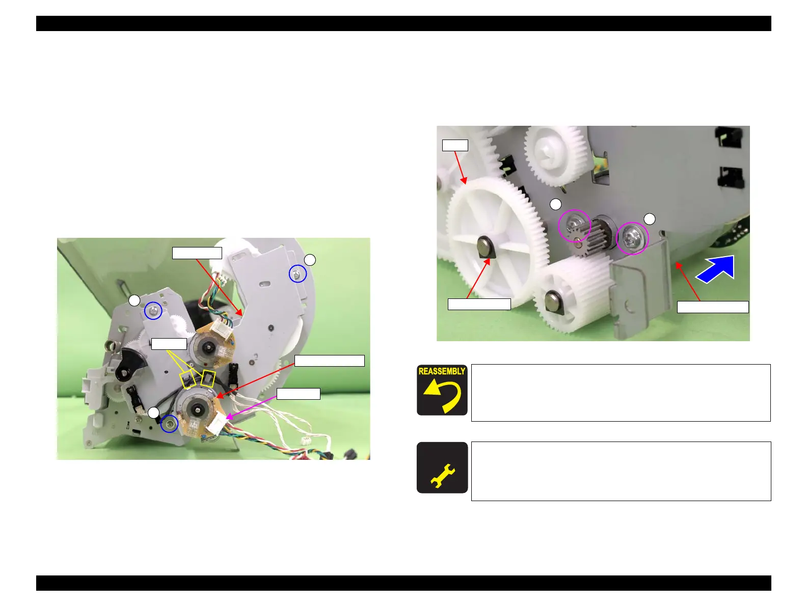
8. Remove the retaining ring, and remove the gear.
9. Remove the two screws that secure the ATC Motor Assy, and remove the ATC
Motor Assy.
B) Silver, Phillips, Round Washer Head S-tite M3x5: two pieces
Figure 3-150. Removing the ATC Motor Assy
ATC Motor Assy
Motor Assy
A
A
A
Connector
Hooks
When installing the ATC Motor Assy, be careful of the installation
direction referring to Figure 3-149.
A D J U S T M E N T
R E Q U I R E D
Be sure to refer to Chapter 4 “Adjustment” (see p277) and perform
specified adjustment after replacing the ATC Motor Assy.
<Adjustment item>
Counter Reset (ATC Motor Counter)
ATC Motor Assy
B
Retaining ring
Gear
B
 Loading...


