Epson Stylus Pro 4900/Epson Stylus Pro 4910 Revision A
DISASSEMBLY & ASSEMBLY Disassembly and Assembly Procedure 232
Confidential
3.4.9.2 Printhead
1. Remove the Front Cover. (p142)
2. Remove the Control Panel Cover. (p136)
3. Remove the Right Upper Cover. (p138)
4. Remove the Right Cover. (p139)
5. Remove the Left Cover. (p137)
6. Unlock the carriage, and move the CR Unit to the left end. (p124)
7. Remove the CR Cover. (p149)
8. Remove the Ink Selector Assy from the CR Unit. (Step 9 to Step 14 in “3.4.9.1 Ink
Selector Assy” (P. 229))
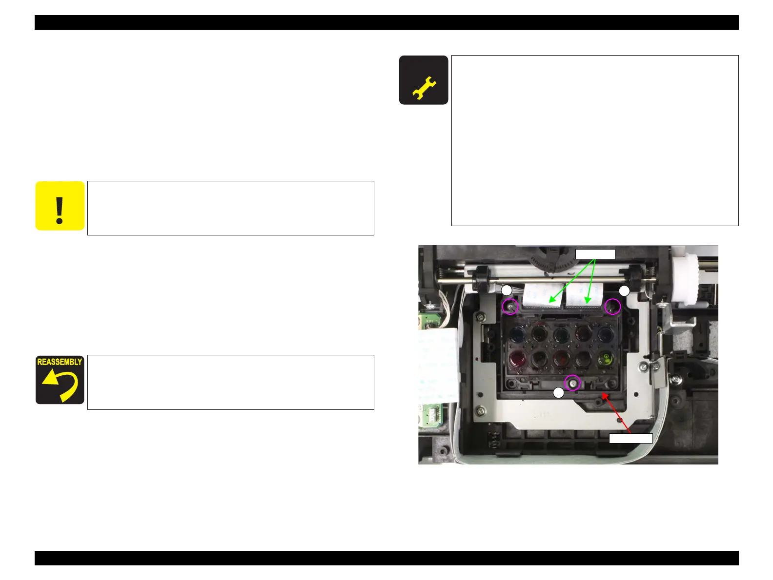
9. Remove the three screws that secure the Printhead.
A) Silver, Phillips, Bind P-tite M2.5x6: three pieces
10. Remove the Printhead, and disconnect the FFC.
Figure 3-165. Removing the Printhead
C A U T I O N
Be sure to move the CR Unit to the left end before performing the
following steps. Performing the following step with the CR on the
platen may damage the Printhead.
After installing the Printhead, be sure to check that the Printhead
does not move by shaking it slightly. If it moves, re-tighten the three
screws securely.
A D J U S T M E N T
R E Q U I R E D
Be sure to refer to Chapter 4 “Adjustment” (see p277) and perform
specified adjustments after replacing or removing the Printhead.
<Adjustment items>
1. Counter Reset (Printhead Counter)
2. Head ID Check & Input
3. PG Height Check & Adjustment
4. Cleaning
5. Nozzle Check
6. AID Function Check
7. CR & PF Direction Head Slant Adjustment
8. PW + T&B&S Check & Adjustment
9. Auto Bi-D Adjustment
10. Colorimetric Calibration Adjustment
A
A
Printhead
A
Head FFC
 Loading...


