Epson Stylus Pro 4900/Epson Stylus Pro 4910 Revision A
DISASSEMBLY & ASSEMBLY Disassembly and Assembly Procedure 267
Confidential
3.4.12.3 Thermistor
1. Remove the Color Measurement Device. (p255)
2. Remove the Mounter. (p132)
3. Remove the Upper Cover. (p257)
4. Remove the I/F Cover. (p258)
5. Remove the Left Cover. (p260)
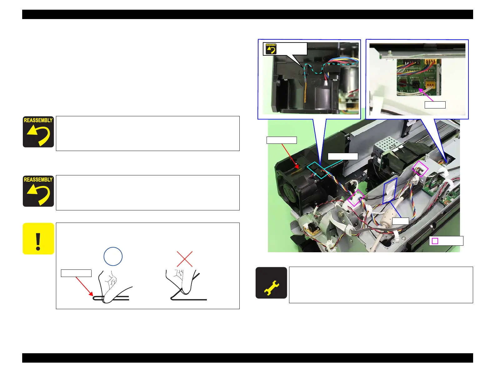
6. Disconnect the connector (CN11) from the Main-C Board.
7. Release the harness from the clamp, tape, and cable guide.
8. Remove the Thermistor.
Figure 3-209. Removing the Thermistor
Use tweezers or a similar tool to connect the connector (CN11).
Make sure to route the harness correctly as shown in Figure 3-209.
C A U T I O N
When removing the Thermistor in the next step, make sure to hold
it by both sides together.
Thermistor
A D J U S T M E N T
R E Q U I R E D
Be sure to refer to Chapter 4 “Adjustment” (see p277) and perform
specified adjustment after replacing or removing the Thermistor.
<Adjustment item>
Spectroproofer Sensor Check
Thermistor
CN11
Tape
Clamp
Cable guide
Routing
 Loading...


