Epson Stylus Pro 4900/Epson Stylus Pro 4910 Revision A
DISASSEMBLY & ASSEMBLY Disassembly and Assembly Procedure 161
Confidential
3.4.3.5 SUB Board
1. Remove the Front Cover. (p142)
2. Remove the Right Upper Cover. (p138)
3. Remove the Control Panel Cover. (p136)
4. Remove the Right Cover. (p139)
5. Remove the CR Cover. (p149)
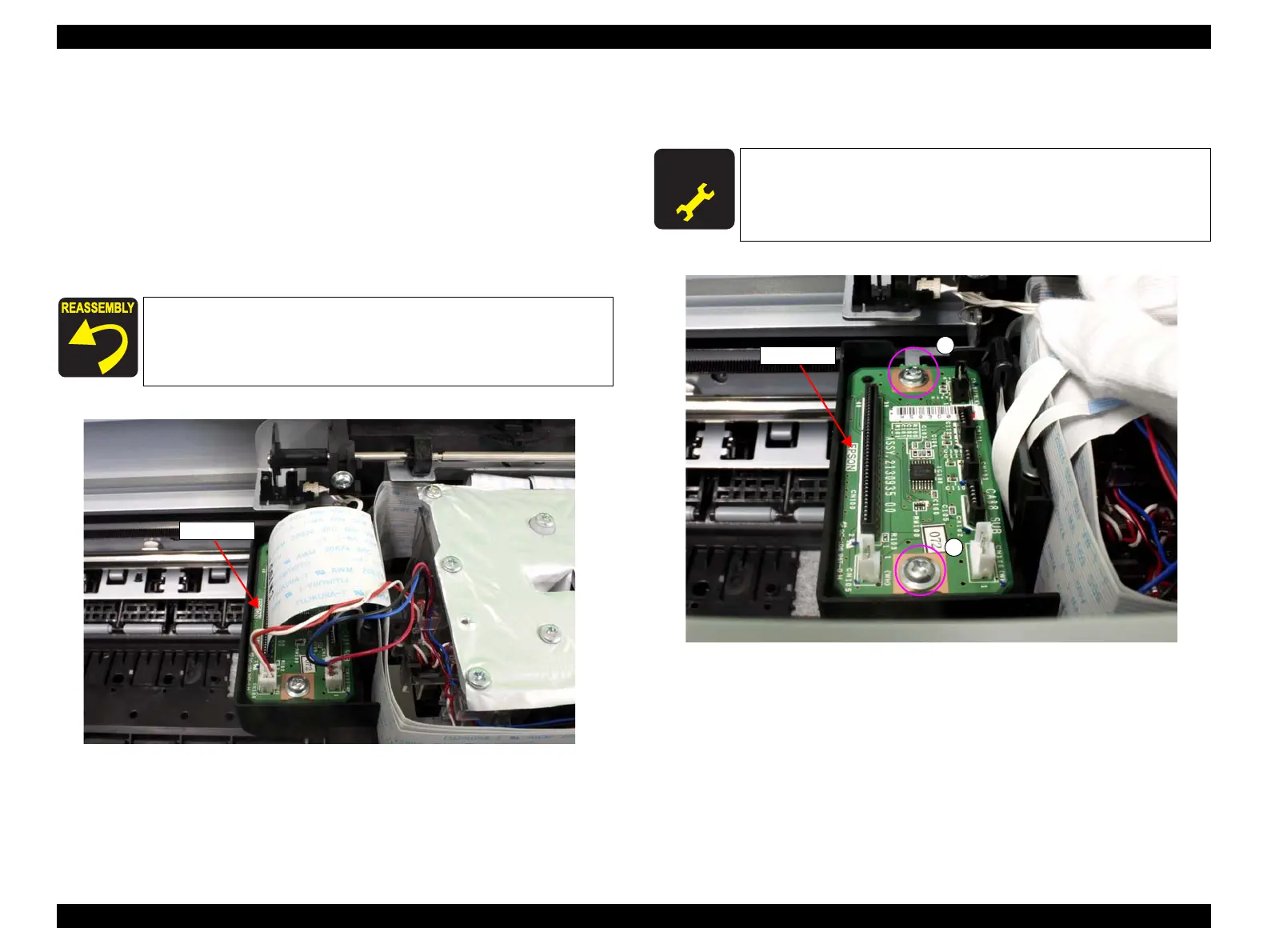
6. Disconnect all the connectors and FFCs on the SUB Board.
Figure 3-65. Disconnecting the connectors
7. Remove the two screws that secure the SUB Board, and remove the SUB Board.
A) Silver, Phillips, Round Washer Head P-tite M3x8: two pieces
Figure 3-66. Removing the SUB Board
When installing the SUB Board, be sure to refer to Chapter 6
“Appendix” (see p432) and connect the connectors correctly.
SUB Board
A D J U S T M E N T
R E Q U I R E D
Be sure to refer to Chapter 4 “Adjustment” (see p277) and perform
specified adjustment after replacing the SUB Board.
<Adjustment item>
Colorimetric Calibration Adjustment
SUB Board
A
A
 Loading...


