Epson Stylus Pro 4900/Epson Stylus Pro 4910 Revision A
DISASSEMBLY & ASSEMBLY Disassembly and Assembly Procedure 166
Confidential
3.4.3.10 LED Board
1. Remove the Front Cover. (p142)
2. Remove the Control Panel Cover. (p136)
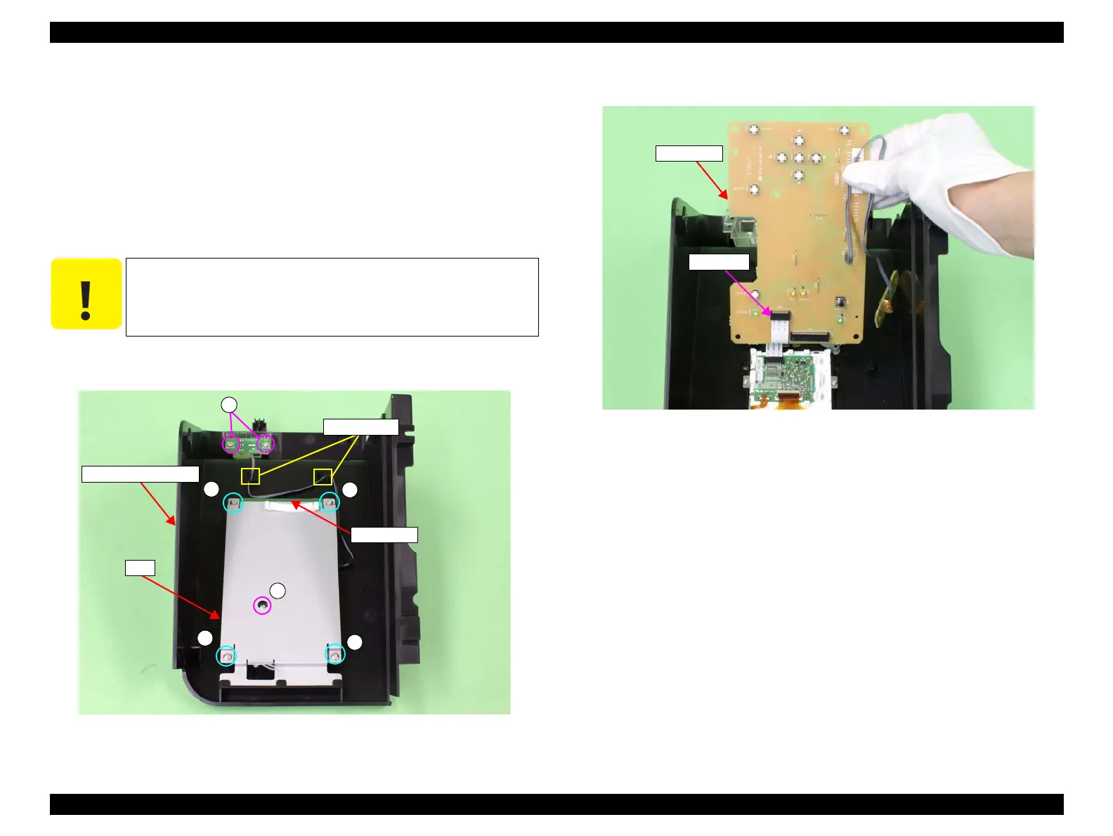
3. Remove the four screws that secure the plate, and remove the plate.
A) Silver, Phillips, Bind machine screw M3x8: four pieces
4. Remove the three screws that secure the LED Board.
B) Silver, Phillips, Bind P-tite M3x8: three pieces
5. Release the harness from the cable guides, and remove the LED Board.
Figure 3-75. Removing the plate
6. Disconnect the FFC on the LED Board, and remove the LED Board.
Figure 3-76. Removing the LED Board
C A U T I O N
When removing the LED Board in the next step, since the FFC is
connected to the LED Board, be sure not to pull it away too far
from the Control Panel Cover.
A
Control Panel Cover
Plate
A
A
A
B
B
Cable guides
LED Board
LED Board
Connector
 Loading...


