Epson Stylus Pro 4900/Epson Stylus Pro 4910 Revision A
DISASSEMBLY & ASSEMBLY Disassembly and Assembly Procedure 272
Confidential
3.4.12.7 Backing Sensor
1. Remove the Color Measurement Device. (p255)
2. Remove the Mounter. (p132)
3. Remove the backing and the white calibration tile. (p256)
4. Remove the Upper Cover. (p257)
5. Open the Front Cover, and move the carriage to the right.
(Step 6 in “3.4.12.5 Paper Pressing Motor” (P. 269))
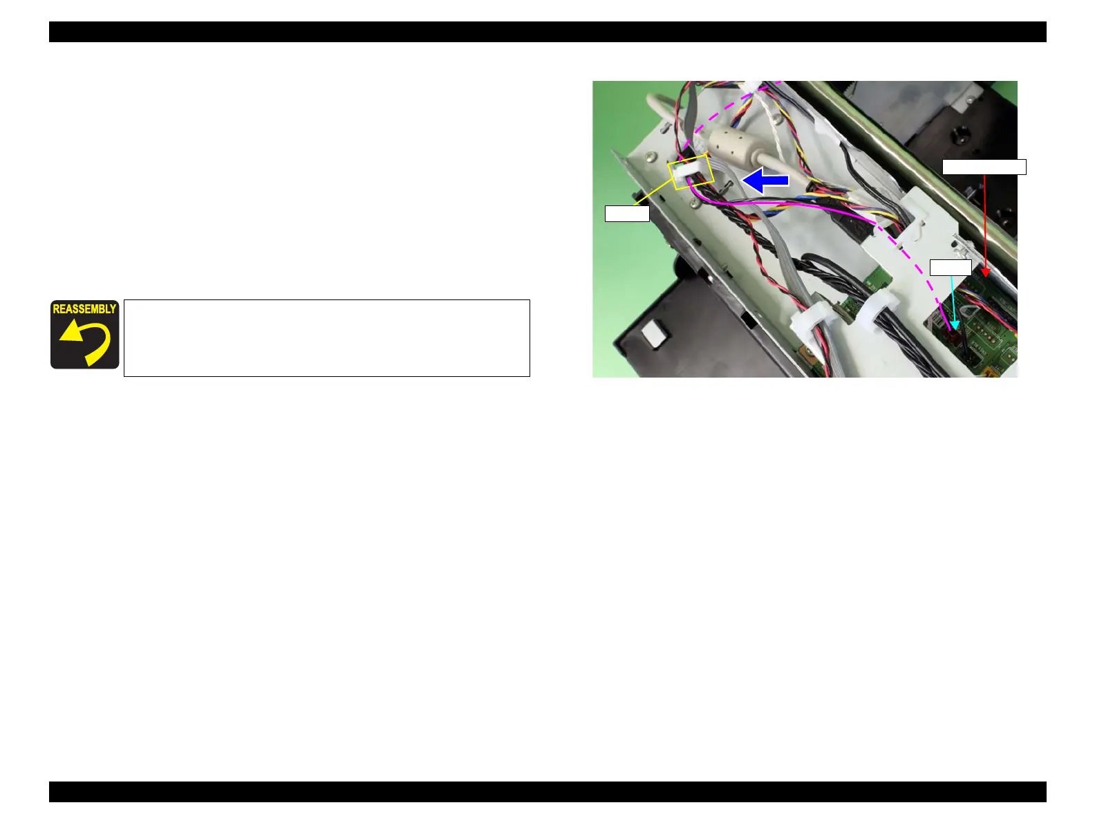
6. Disconnect the connector (CN15) from the Main-C Board.
7. Release the harness from the clamp, and pull it out in the direction of the arrow.
Figure 3-215. Pulling out the harness
Use tweezers or a similar tool to connect the connector (CN15).
CN15
Clamp
Main-C Board
 Loading...


