Epson Stylus Pro 4900/Epson Stylus Pro 4910 Revision A
DISASSEMBLY & ASSEMBLY Disassembly and Assembly Procedure 140
Confidential
3.4.2.7 Left IC Cover Frame/Right IC Cover Frame/
Left IC Sensor/Right IC Sensor
1. Open the Right IC Cover.
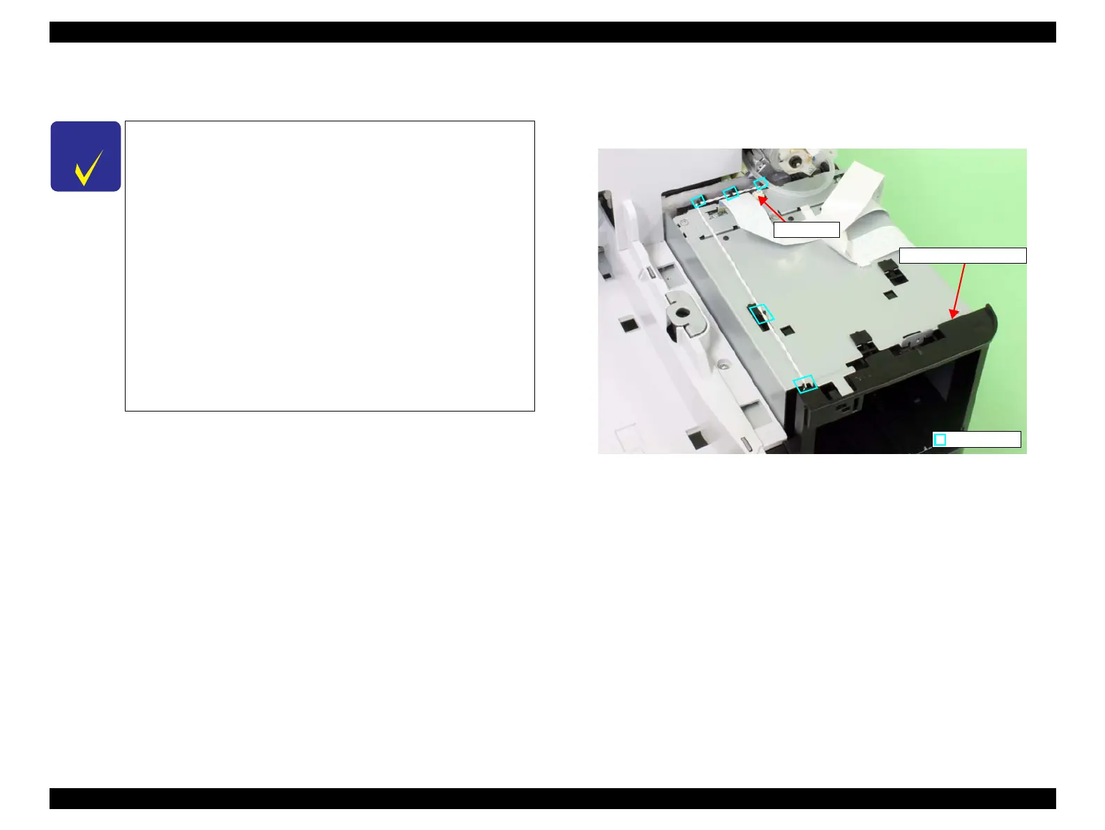
2. Disconnect the connector of the Right IC Sensor, and release the harness from the
cable guides.
Figure 3-38. Disconnecting the connector
C H E C K
P O I N T
Basically you can remove these parts on the left and the ones on the
right in the same way. Therefore this section describes the way to
remove the parts on the right only. However, the parts that have to
be removed before removing these parts differ.
Left IC Cover
• Front Cover (p142)
• Right Upper Cover (p138)
• Control Panel Cover (p136)
• Right Cover (p139)
• Left Cover (p137)
• Media Eject Cover (p148)
Right IC Cover
• Front Cover (p142)
• Right Upper Cover (p138)
• Control Panel Cover (p136)
• Right Cover (p139)
Connector
Cable guide
Right IC Cover Frame
 Loading...


