Epson Stylus Pro 4900/Epson Stylus Pro 4910 Revision A
DISASSEMBLY & ASSEMBLY Disassembly and Assembly Procedure 162
Confidential
3.4.3.6 SUB-B Board
1. Remove the Front Cover. (p142)
2. Remove the Right Upper Cover. (p138)
3. Remove the Control Panel Cover. (p136)
4. Remove the Right Cover. (p139)
5. Remove the Rear Cover. (p144)
6. Remove the Mid-Right Cover. (p150)
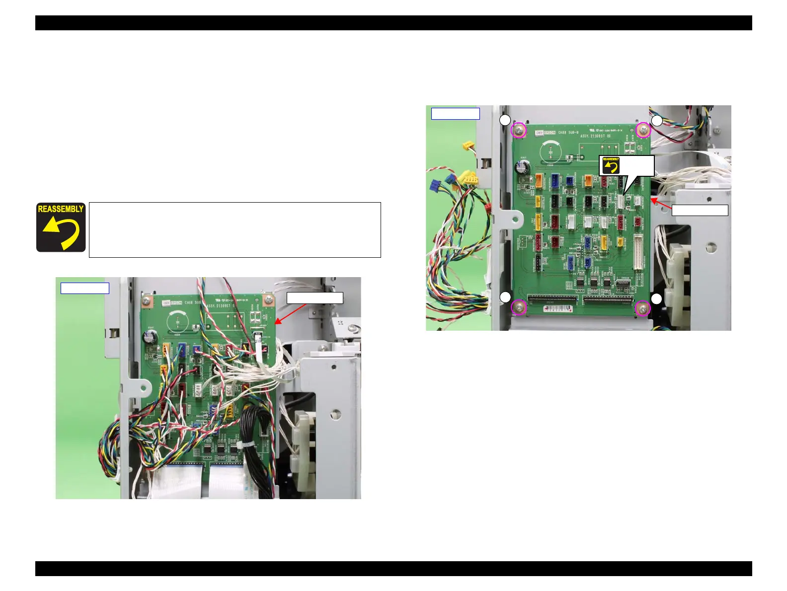
7. Disconnect all the connectors and FFCs on the SUB-B Board.
Figure 3-67. Disconnecting the connectors
8. Remove the four screws that secure the SUB-B Board, and remove the SUB-B
Board.
A) Silver, Phillips, Bind machine screw M3x6: four pieces
Figure 3-68. Removing the SUB-B Board
The connector shown in Figure 3-68 is not used.
When installing the SUB-B Board, be sure to refer to Chapter 6
“Appendix” (see p432) and connect the connectors correctly.
SUB-B Board
- Rear left -
SUB-B Board
A
- Rear left -
A
A
A
Unused
 Loading...


