Epson Stylus Pro 4900/Epson Stylus Pro 4910 Revision A
DISASSEMBLY & ASSEMBLY Disassembly and Assembly Procedure 147
Confidential
3.4.2.13 Board Tray
1. Remove the Rear Unit. (p145)
2. Remove the Rear Cover. (p144)
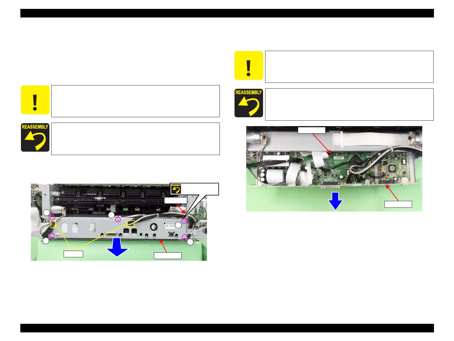
3. Remove the five screws that secure the Board Tray.
A) Silver, Phillips, Round Washer Head S-tite M3x8: five pieces
4. Pull out the Board Tray slightly to the rear.
5. Release the harnesses from the two saddles.
Figure 3-48. Removing the screws
6. Disconnect all connectors and FFCs on the Main Board, and remove the Board
Tray.
Figure 3-49. Removing the Board Tray
C A U T I O N
The Main Board and Network Board are stored in the Board Tray
and they are connected to the harnesses from the main body.
Therefore, be careful not to pull out the Board Tray too far from
the main body in the next step.
Secure the cable tie and the plate with the same screw shown in the
figure.
Screw together
A
A
A
A
A
Saddles
Cable tie
Board Tray
C A U T I O N
Be extremely careful not to insert FFCs at an angle in connectors.
Doing so may cause serious damage to the terminals inside the
connectors, and it can lead to big trouble of the circuit components.
When installing the Main Board, be sure to refer to Chapter 6
“Appendix” (see p432) and connect the connectors correctly.
Main Board
Board Tray
 Loading...


