Epson Stylus Pro 4900/Epson Stylus Pro 4910 Revision A
DISASSEMBLY & ASSEMBLY Disassembly and Assembly Procedure 265
Confidential
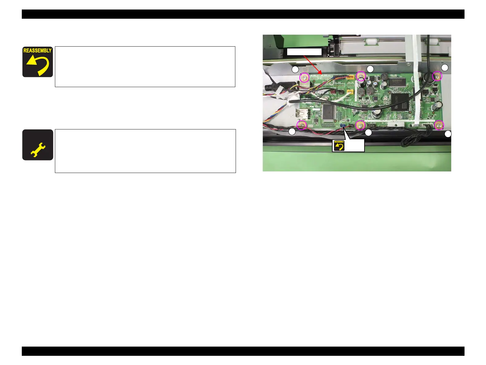
10. Disconnect all connectors and FFCs on the Main-C Board.
11. Remove the six screws that secure the Main-C Board, and remove the Main-C
Board.
D) Silver, Phillips, Bind machine screw M3x6: six pieces
Figure 3-207. Removing the Main-C Board
One of the connectors is unused. See Figure 3-207.
Make sure to connect all connectors and FFCs to the Main-C
Board before installing the plate.
When installing the Main-C Board, be sure to refer to Chapter
5 “Appendix (see p409) and connect the connector correctly.
A D J U S T M E N T
R E Q U I R E D
Be sure to refer to Chapter 4 “Adjustment” (see p277) and perform
specified adjustments after replacing the Main-C Board.
<Adjustment items>
1. NVRAM Backup
2. Spectroproofer Serial Number Check & Input
Main-C Board
Unused
D
D
D
D
D
D
 Loading...


